&' /&' &RPPHUFLDO 'LVSOD\ 8VHU *XLGH *XLGH GH O¶XWLOLVDWHXU *XtD GHO XVXDULR %HGLHQXQJVDQOHLWXQJ 3\ɤɨɜɨɞɫɬɜɨ ɩɨɥɶɡɨɜɚɬɟɥɹ ĮġٺҢЙы 0RGHO 1R 96
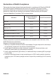
'HFODUDWLRQ RI 5R+6 &RPSOLDQFH 7KLV SURGXFW KDV EHHQ GHVLJQHG DQG PDQXIDFWXUHG LQ FRPSOLDQFH ZLWK 'LUHFWLYH (& RI WKH (XURSHDQ 3DUOLDPHQW DQG WKH &RXQFLO RQ UHVWULFWLRQ RI WKH XVH RI FHUWDLQ KD]DUGRXV VXEVWDQFHV LQ HOHFWULFDO DQG HOHFWURQLF HTXLSPHQW 5R+6 'LUHFWLYH DQG LV GHHPHG WR FRPSO\ ZLWK WKH PD[LPXP FRQFHQWUDWLRQ YDOXHV LVVXHG E\ WKH (XURSHDQ 7HFKQLFDO $GDSWDWLRQ &RPPLWWHH 7$& DV VKRZQ EHORZ 3URSRVHG 0D[LPXP &RQFHQWUDWLRQ $FWXDO &RQFHQWUDWLRQ /HDG 3E 0HUFXU\ +J
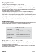
&RS\ULJKW ,QIRUPDWLRQ &RS\ULJKW 9LHZ6RQLF &RUSRUDWLRQ $OO ULJKWV UHVHUYHG 9LHZ6RQLF WKH WKUHH ELUGV ORJR 2Q9LHZ 9LHZ0DWFK DQG 9LHZ0HWHU DUH UHJLVWHUHG WUDGHPDUNV RI 9LHZ6RQLF &RUSRUDWLRQ (1(5*< 67$5 LV D UHJLVWHUHG WUDGHPDUN RI WKH 8 6 (QYLURQPHQWDO 3URWHFWLRQ $JHQF\ (3$ $V DQ (1(5*< 67$5 SDUWQHU 9LHZ6RQLF &RUSRUDWLRQ KDV GHWHUPLQHG WKDW WKLV SURGXFW PHHWV WKH (1(5*< 67$5 JXLGHOLQHV IRU HQHUJ\ HI¿FLHQF\ 'LVFODLPHU 9LHZ6RQLF &RUSRUDWLRQ VKDOO QRW EH OLDEOH IRU WHFKQLFDO RU H
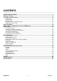
CONTENTS ——————————————————————————————————————————————— SAFETY INSTRUCTIONS ...............................................................................................................3 Package Contents ..........................................................................................................................9 Parts Name and Functions..........................................................................................................10 Control Panel ................................
SAFETY INSTRUCTIONS WARNINGS AND PRECAUTIONS KNOW THESE SAFETY SYMBOLS CAUTION: TO REDUCE THE RISK OF ELECTRIC SHOCK, DO NOT REMOVE COVER (OR BACK). NO USER SERVICEABLE PARTS INSIDE. REFER SERVICING TO QUALIFIED SERVICE PERSONNEL. This symbol indicates high voltage is present inside. It is dangerous to make any kind of contact with any inside part of this product. This symbol alerts you that important literature concerning operation and maintenance has been included with this product.
REGULATORY INFORMATION CE DECLARATION OF CONFORMITY MMD declare under our responsibility that the product is in conformity with the following standards • EN60950-1:2006+A11:2009 (Safety requirement of Information Technology Equipment) • EN55022:2006+A1:2007 (Radio Disturbance requirement of Information Technology Equipment) • EN55024:1998+A1:2001+A2:2003 (Immunity requirement of Information Technology Equipment) • EN6100-3-2: 2006 (Limits for Harmonic Current Emission) • EN6100-3-3:1995+A1:2001+A2:2005 (Lim
POLISH CENTER FOR TESTING AND CERTIFICATION NOTICE The equipment should draw power from a socket with an attached protection circuit (a three-prong socket). All equipment that works together (computer, monitor, printer, and so on) should have the same power supply source. The phasing conductor of the room’s electrical installation should have a reserve short-circuit protection device in the form of a fuse with a nominal value no larger than 16 amperes (A).
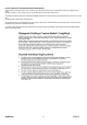
INFORMATION FOR UK ONLY WARNING - THIS APPLIANCE MUST BE EARTHED. Important: This apparatus is supplied with an approved moulded 13A plug. To change a fuse in this type of plug proceed as follows: 1. Remove fuse cover and fuse. 2. Fit new fuse which should be a BS 1362 5A,A.S.T.A. or BSI approved type. 3. Refit the fuse cover. If the fitted plug is not suitable for your socket outlets, it should be cut off and an appropriate 3-pin plug fitted in its place.
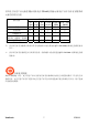
中国电子信息产品污染控制标识要求(中国RoHS法规标示要求)产品中有毒有害物质或 元素的名称及含量 铅 (Pb) ○ 有毒有害物质或元素 汞 镉 六价铬 多溴联苯 多溴二苯醚 (Hg) (Cd) (Cr 6+) (PBB) (PBDE) ○ ○ ○ ○ ○ × × 部件名称 外壳 液晶面板 × 电路板组件 附件 × (遥控器、电源线、连接线) 遥控器电池 × ○ ○ ○ ○ ○ ○ ○ ○ ○ ○ ○ ○ ○ ○ ○ ○ ○ ○ ○ ○: 表示该有毒有害物质在该部件所有均质材料中的含量均在SJ/T11363-2006标准规定的限量要求 以下。 ×: 表示该有毒有害物质至少在该部件的某一均质材料中的含量超出SJ/T11363-2006 标准规定的限 量要求。 环保使用期限 此标识指期限(十年),电子信息产品中含有的有毒有害物质或元素在正常使用的条件下不会发生外 泄或突变,电子信息产品用户使用该电子信息产品不会对环境造成严重污染或对其人身、财产造成 严重损害的期限。 ViewSonic 7 CD5233
NORTH EUROPE (NORDIC COUNTRIES) INFORMATION Placering/Ventilation VARNING: FÖRSÄKRA DIG OM ATT HUVUDBRYTARE OCH UTTAG ÄR LÄTÅTKOMLIGA, NÄR DU STÄLLER DIN UTRUSTNING PÅPLATS. Placering/Ventilation ADVARSEL: SØRG VED PLACERINGEN FOR, AT NETLEDNINGENS STIK OG STIKKONTAKT ER NEMT TILGÆNGELIGE. Paikka/Ilmankierto VAROITUS: SIJOITA LAITE SITEN, ETTÄ VERKKOJOHTO VOIDAAN TARVITTAESSA HELPOSTI IRROTTAA PISTORASIASTA.
Package Contents The • • • LCD monitor pack* should include: LCD monitor Power cord (1.8 m) VGA Signal Cable (1.8 m) • • CD User Manual & QSG Remote Control and AAA Batteries • • • • Main switch cover Screw for Main Switch cover x2 Clamper x 2 Screw for Clamper x 2 Xxxxxxxxxxxx xx xxxxxxxxxxxx xxxxxxxxxxxx xxxxxxxxx CD User Manual & QSG Screw for Main switch cover (M3 x 5) x 2 Main switch cover Remote Control and AAA Batteries * The supplied power cord varies depending on destination.
Parts Name and Functions Control Panel POWER button ( ) : To switch the power on/off. MUTE button : To switch the audio mute ON/OFF. SOURCE button : To set the function while OSD menu is on or to activate input selection menu while OSD menu is off. off. off.
Terminal Panel EXTERNAL CONTROL (mini D-Sub 9 pin) This is for serial connection when multiple monitors are connected. To achieve remote management through RS232 commands (refer to the RS232 remote control user manual), connect the RS-232C OUT connector from a computer or from a different monitor to the RS-232C IN connector from your monitor. The same RS-232C commands can be looped through by connecting the RS-232C OUT of this monitor to the next RS-232C IN.
Remote Control MENU button To turn the OSD menu on/off. DOWN button To move the highlight bar down to adjust the selected item when OSD menu is on. To move the sub-picture down when in “PIP” mode. INFO. button To turn on/off the setting information displayed on the right-up corner of the screen. SIZE button To select the picture size from [FULL], [NORMAL], [CUSTOM] , [DYNAM IC] and [REAL]. VOLUME button VOL+ button: To increase the audio output level.
Operating Range for the Remote Control Handling the remote control Point the top of the remote control towards the LCD monitor's remote sensor during button operation. Use the remote control within a distance of about 7 m/ 23 ft from the front of the LCD monitor's remote control sensor and within a horizontal and vertical angle 30° with a distance of about 3 m/ 10 ft. * * * * Do not subject to strong shock. Do not allow water or other liquid to splash the remote control.
Setup Procedure 1. Install the system on the right location CAUTION: THE LCD MONITOR MUST BE MOVED OR INSTALLED BY TWO OR MORE PERSONS. Failure to follow this caution may result in injury and damage when the LCD monitor falls. CAUTION: DO NOT ATTEMPT TO INSTALL THE LCD MONITOR BY YOURSELF. The LCD display must be installed by a qualified technician. Contact your dealer for more information. CAUTION: DO NOT MOUNT OR OPERATE THE DISPLAY UPSIDE DOWN, FACE UP OR FACE DOWN.
9. Adjust the image Make adjustments to brightness or contrast if required. 10. Recommended Adjustment To reduce the risk of “image persistence”, please adjust the following items based on the application being used. “POWER SAVE”, “PANEL SAVING”, “DATE AND TIME”. 11. To prevent the main power switch from being changed To prevent the possibility of main power switch being carelessly pushed, please attach the main switch cover (accessory) onto it.
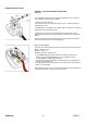
How to Mount and Attach Feet to the LCD Monitor You can install the LCD monitor in one of the following two ways: Method 1: Attach and remove the optional stands How to install stands 1. Please turn the monitor off. 2. After inserting stand in guide block, fasten the thumbscrews on both sides of the monitor. NOTE: Install the table stand with the longer end of the feet directing to the front. In the upright position How to remove the stands 1. Spread the protective sheet on the flat surface. 2.
To avoid monitor from falling Take measures to prevent the monitor from falling over in case of an earthquake or other disaster might occur to lessen the probability of injury and damage. As shown in the figure below, secure the monitor to a solid wall or pillar using rope (commercially available) strong enough to bear the weight of the monitor( approx. 47.5 kg). Screw hooks (commercially available), of ring type rather than C-shaped screw hooks (with opening), are recommended. Screw here is not supplied.
Ventilation Requirements for enclosure locating To allow heat to disperse, leave space between surrounding objects as shown in the diagram below.
Connectivity Before making connections: * * First turn off the power of all the attached equipments before make connections. Refer to the user manual included in each separate piece of equipment.
Connecting to a Personal Computer As you finish the connection between the computer and the LCD monitor, you could play the contents in the computer and display them on the LCD monitor. Connecting the LCD Monitor to a Personal Computer • To achieve this, apply the supplied VGA signal cable (mini D-sub 15 pin to mini D-sub 15 pin) to make connection between a PC and the LCD monitor (VGA IN connector).
Connecting to a Digital Interface Equipment Connections can be made between the LCD monitor and other digital equipment that is equipped with a digital interface compliant with the DVI (Digital Visual Interface) standard. Connect the LCD Monitor to a Computer with a Digital Output • The HDMI , DVI-D IN connector accepts a HDMI cable. • HDMI and DVI-D can receive HDMI video signals from either a HDMI output of for instance a DVD player or from a DVI-D output of a PC.
Connecting to a DVD Player As you finish the connection between the DVD player and the LCD monitor, you could display the contents from the played DVD on the LCD monitor. You might like to refer to your DVD player’s manual for further information. Connect the LCD Monitor to a DVD Player • To achieve this, apply a 3x components cable (Y, Pb, Pr) with BNC connectors at one end and RCA connectors at the other end between DVD player and display.
Connecting to a Stereo Amplifier You can connect your stereo amplifier to your LCD monitor. Refer to your amplifier's manual for further information. Connect the LCD Monitor to a Stereo Amplifier • Turn on the LCD monitor and the amplifier only after all connections have been finished. • Apply 2 RCA cables (audio left and right) to make connection between the amplifier (audio in) and the LCD monitor (audio out). • Do not reverse the audio left and right jacks.
Basic Operation Power ON and OFF Modes The LCD monitor power indicator will turn green while powered on and will turn red while powered off. The monitor can be powered on or off using the following three options: 1. Pressing the Main Power Switch. NOTE: When the Main Power Switch is used to power off the LCD monitor, the remote control, the power button and the indicator will not work. Make sure to turn the Main Power Switch on before using the other two options. 2. Pressing the power button.
Power Indicator Status Green Red LED Off Red Blinking * See troubleshooting Power ON Power Standby Power OFF Diagnosis (Detecting failure) Using Power Management Please turn off the LCD monitor when it will not be used for long time. This could potentially increase the life and decrease the power consumption of the LCD monitor. Standby mode: Push the power button on the remote control or on the monitor to enter the standby mode. Power Off: Push the Main Power Switch to enter the power off mode.
Smart Picture Mode HDMI, VGA HIGHBRIGTH STANDARD sRGB COMPONENT, VIDEO HIGHBRIGTH STANDARD CINEMA Audio Source Switching You can select the audio source using the AUDIO SOURCE button on the remote control. HDMI HDMI AUDIO1 AUDIO2 AUDIO3 Control Lock Mode This function disables the operation o buttons so that the adjustments you make are not active when they are pressed. To disable the buttons, press and hold down the and buttons together for at least 3 seconds.
OSD (On-Screen-Display) Controls Remote Control Control Panel Press MENU button to open Main menu. Press UP or DOWN button to select submenu. Press EXIT button to open Main menu. Press UP or DOWN button to select. UP or DOWN button Press ENTER button to enable setting. Press UP or DOWN, and LEFT or RIGHT button to select function, or adjust the setting. Press ENTER button to enable the setting. Press SOURCE button Press UP or DOWN, and LEFT to enable the setting.
Main-Menu PICTURE BRIGHTNESS Adjusts the overall image and background screen brightness. Press ▶ button to increase brightness. Press ◀ button to decrease brightness. CONTRAST Adjusts the image brightness for the input signal. Press ▶ button to increase contrast. Press ◀ button to decrease contrast. SHARPNESS This function is digitally capable to keep crisp images at any timing. It is adjustable to get a distinct image or a soft one as you prefer and set independently for each picture mode.
COLOR * : INPUT HDMI , DVI-D(INPUT MODE-HD), COMPONENT, S-VIDEO, VIDEO only Adjusts the color of the screen. Press + button to increase color depth. Press - button to decrease color depth. COLOR TEMPERATURE Is used to adjust the color temperature. The image becomes reddish as the color temperature decreases, and becomes bluish as the color temperature increases. COLOR CONTROL The color levels of red, green, and blue are adjusted by the color bars.
Main-Menu SCREEN H POSITION Controls Horizontal Image position within the display area of the LCD. Press ▶ button to move screen to right. Press ◀ button to move screen to left. V POSITION Controls Vertical Image position within the display area of the LCD. Press ▶ button to move screen to UP. Press ◀ button to move screen to DOWN. CLOCK * : INPUT VGA only Press ▶ button to expand the width of the image on the screen the right. Press ◀ button to narrow the width of the image on the screen the left.
CUSTOM ZOOM “CUSTOM ZOOM” will be selected when you select “CUSTOM” on the screen “ZOOM” mode. ZOOM: expands the horizontal and the vertical size simultaneously. HZOOM: expands the horizontal size only. VZOOM: expands the vertical size only. H POSITION: moves to the right with + button. moves to the left with – button. V POSITION: moves up with + button. moves down with – button. SCREEN RESET Selecting Screen reset allows you to reset all OSD settings from PICTURE setting.
Main-Menu AUDIO BALANCE Adjusts the balance of L/R volume. Press ▶ button to move the stereo sound image to right. Sound of the left side will be small. Press ◀ button to move the stereo sound image to left. TREBLE This feature helps you to accentuate or reduce the high frequency sound. Press ▶ button to increase TREBLE sound. Press ◀ button to decrease TREBLE sound. BASS This feature helps you to accentuate or reduce the low frequency sound. Press ▶ button to increase BASS sound.
Main-Menu PIP (PICTURE IN PICTURE) Note: The “PIP” and “POP” modes do not function when the screen size is “CUSTOM” or “REAL”. PIP SIZE Selecting the size of picture inserted at the “Picture-in-Picture” (PIP) mode. “Large”, “Middle” and “Small” are available. PIP AUDIO Selecting the sound source in PIP mode. When selecting “MAIN AUDIO”, you will get the sound for the main picture and when selecting “PIP AUDIO”, you will get the sound for the picture instead.
Main-Menu CONFIGURATION 1 AUTO ADJUST * : INPUT VGA only Press "ENTER" button to automatically adjust screen size, horizontal position, vertical position, clock, clock phase, white level and black level. Press " EXIT " button to cancel execution AUTO ADJUST and then will return to the previous menu. POWER SAVE Selecting RGB "ON", the monitor will go to power management mode when HDMI, DVI-D,VGA, sync is lost.
FACTORY RESET Selecting "YES" allows you to reset PICTURE, SCREEN, AUDIO, CONFIGURATION1,2 and ADVANCED OPTION will be back to factory settings (except LANGUAGE, DATE AND TIME and SCHEDULE). Select "YES" and press "ENTER" button to restore the factory preset data. Press " EXIT " button to cancel and return the previous menu.
Main-Menu CONFIGURATION 2 OSD TURN OFF The OSD control menu will stay on as long as it is used. In the OSD Turn Off submenu, you can select how long the monitor waits after the last touch of a button to shut off the OSD control menu. The preset choices are 5 -120 seconds. INFORMATION OSD Selects the information OSD to be displayed or not. The information OSD will be displayed when the input signal is changed or a source change or warning message like no-signal or out-of range.
Main-Menu ADVANCED OPTION INPUT RESOLUTION * : INPUT VGA only This feature makes the display controlling the source in order to match display capabilities by choice or automatically. You can select one of the following timings: (1)1024x768, 1280x768, 1360x768 and 1366x768. (2) 640x480, 720x480 and 852x480 (3) 800x600, 1064x600 and 720x576 (4) 1400x1050 and 1864x1050 (5) 720x400 and 640x400 AUTO: Determines the resolution automatically.
FILM MODE * : INPUT HDMI, DVI-D(MODE-HD), S-VIDEO, VIDEO only Selects Film mode function. AUTO: Enable the Film mode function. This mode is better suited for movies, which is converted 24 Frames/sec source to DVD Video. We recommend to select “PROGRESSIVE” in “SCAN CONVERSION”. OFF: Disable the Film mode function. This mode is better suited for Broadcasting or VCR source. IR CONTROL Selects the operation mode of the remote controller when multiple monitors are connected via RS232C.
SCHEDULE Programs the monitor's working schedule. Schedules the power on and power off by using hour and a day of the week. Also sets the input port. This OSD can't be removed except EXIT. MONITOR ID ID numbers for remote control are assigned to monitors that are multi-connected via RS232C. ID numbers 1 to 26 are selectable. DDC/CI Use to turn ON or OFF the DDC/CI communication function. Select ON for normal use.
NOTE NOTE 1: IMAGE PERSISTENCE Please be aware that LCD Technology may experience a phenomena known as Image Persistence. Image Persistence occurs when residual or “ghost” image of a previous image remains visible on the screen. Unlike CRT monitors, LCD monitors’ image persistence is not permanent, but constant images being displayed for a long period of time should be avoided. To alleviate image persistence, turn off the monitor for as long as the previous image was displayed.
NOTE 3: “PIP”, “POP” and “SIDE BY SIDE” The following table shows the combination of signal inputs under which the “PIP” and “POP” modes function. These modes do not function, however, when the screen size is “CUSTOM” or “REAL”.
Features Full HD LCD display 1920x1080p This display has a resolution that is referred to as Full HD. The state-of-the-art LCD screen technology has the full high-definition widescreen resolution of 1080 progressive lines, each with 1920 pixels. This allows the best possible picture quality for HD input signals with up to 1080 lines. It produces brilliant flicker-free progressive scan pictures with optimum brightness and superb colors.
Troubleshooting No picture • • • • • • The signal cable should be completely connected to the graphics card/computer. Front Power Switch and computer power switch should be in the ON position. Check to make sure that a supported mode has been selected on the graphics card or system being used. (Please consult graphics card or system manual to change graphics mode.) Check the monitor and your graphics card with respect to compatibility and recommended settings.
No Sound • • • Check to see if speaker cable is properly connected. Check to see if mute is activated. Check to see if volume is set at minimum. Remote Control does not work • • • Check the Remote Control’s batteries status. Check if batteries are inserted correctly. Check if the Remote Control is pointing at the monitor’s remote sensor. “SCHEDULE” / “SLEEP TIMER” function is not working properly • • The “SCHEDULE” function will be disabled when the “SLEEP TIMER” is set.
Specifications Specifications Product Specifications LCD Module Frequency Pixel Clock Viewable Size Input Signal PC-Input: Analog Input Diagonal: Pixel Pitch: Resolution: Color: Brightness: Contrast Ratio: Response time: View Angle: Horizontal: Vertical: Video: Sync: Input-terminal: VIDEO Input: AUDIO Input: RS-232C: Output Signal PC-Output: VIDEO Output: AUDIO Output: Speaker Output: RS-232C: Resolutions Supported In: Digital Input 52" / 132.0 cm 0.60 mm 1920 x 1080 dots 1.
&XVWRPHU 6XSSRUW )RU WHFKQLFDO VXSSRUW RU SURGXFW VHUYLFH VHH WKH WDEOH EHORZ RU FRQWDFW \RXU UHVHOOHU 1RWH
/LPLWHG :DUUDQW\ 9,(:621,& /&' &RPPHUFLDO 'LVSOD\ :KDW WKH ZDUUDQW\ FRYHUV 9LHZ6RQLF ZDUUDQWV LWV SURGXFWV WR EH IUHH IURP GHIHFWV LQ PDWHULDO DQG ZRUNPDQVKLS XQGHU QRUPDO XVH GXULQJ WKH ZDUUDQW\ SHULRG ,I D SURGXFW SURYHV WR EH GHIHFWLYH LQ PDWHULDO RU ZRUNPDQVKLS GXULQJ WKH ZDUUDQW\ SHULRG 9LHZ6RQLF ZLOO DW LWV VROH RSWLRQ UHSDLU RU UHSODFH WKH SURGXFW ZLWK D OLNH SURGXFW 5HSODFHPHQW SURGXFW RU SDUWV PD\ LQFOXGH UHPDQXIDFWXUHG RU UHIXUELVKHG SDUWV RU FRPSRQH
0H[LFR /LPLWHG :DUUDQW\ 9,(:621,& /&' &RPPHUFLDO 'LVSOD\ :KDW WKH ZDUUDQW\ FRYHUV 9LHZ6RQLF ZDUUDQWV LWV SURGXFWV WR EH IUHH IURP GHIHFWV LQ PDWHULDO DQG ZRUNPDQVKLS XQGHU QRUPDO XVH GXULQJ WKH ZDUUDQW\ SHULRG ,I D SURGXFW SURYHV WR EH GHIHFWLYH LQ PDWHULDO RU ZRUNPDQVKLS GXULQJ WKH ZDUUDQW\ SHULRG 9LHZ6RQLF ZLOO DW LWV VROH RSWLRQ UHSDLU RU UHSODFH WKH SURGXFW ZLWK D OLNH SURGXFW 5HSODFHPHQW SURGXFW RU SDUWV PD\ LQFOXGH UHPDQXIDFWXUHG RU UHIXUELVKHG SDUWV RU FRPSRQHQWV DFFHVVRULHV +RZ ORQJ WK
&RQWDFW ,QIRUPDWLRQ IRU 6DOHV $XWKRUL]HG 6HUYLFH &HQWUR $XWRUL]DGR GH 6HUYLFLR ZLWKLQ 0H[LFR 1DPH DGGUHVV RI PDQXIDFWXUHU DQG LPSRUWHUV 0p[LFR $Y GH OD 3DOPD 3LVR 'HVSDFKR &RUSRUDWLYR ,QWHUSDOPDV &RO 6DQ )HUQDQGR +XL[TXLOXFDQ (VWDGR GH 0p[LFR 7HO KWWS ZZZ YLHZVRQLF FRP OD VRSRUWH LQGH[ KWP 1Ò0(52 *5$7,6 '( $6,67(1&,$ 7e&1,&$ 3$5$ 72'2 0e;,&2 +HUPRVLOOR 'LVWULEXFLRQHV \ 6HUYLFLRV &RPSXWDFLRQDOHV 6$ GH &9 &DOOH -XDUH] ORFDO &RO %XJDPELOLDV &