CDE5510 Commercial Display User Guide IMPORTANT: Please read this User Guide to obtain important information on installing and using your product in a safe manner, as well as registering your product for future service. Warranty information contained in this User Guide will describe your limited coverage from ViewSonic Corporation, which is also found on our web site at http:// www.viewsonic.com in English, or in specific languages using the Regional selection box in the upper right corner of our website.
Thank you for choosing ViewSonic As a world leading provider of visual solutions, ViewSonic is dedicated to exceeding the world’s expectations for technological evolution, innovation, and simplicity. At ViewSonic, we believe that our products have the potential to make a positive impact in the world, and we are confident that the ViewSonic product you have chosen will serve you well.
Compliance Information NOTE: This section addresses all connected requirements and statements regarding regulations. Confirmed corresponding applications shall refer to nameplate labels and relevant markings on unit. FCC Statement This device complies with Part 15 of the FCC Rules. Operation is subject to the following two conditions: (1) this device may not cause harmful interference, and (2) this device must accept any interference received, including interference that may cause undesired operation.
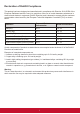
Declaration of RoHS2 Compliance This product has been designed and manufactured in compliance with Directive 2011/65/EU of the European Parliament and the Council on restriction of the use of certain hazardous substances in electrical and electronic equipment (RoHS2 Directive) and is deemed to comply with the maximum concentration values issued by the European Technical Adaptation Committee (TAC) as shown below: Substance Proposed Maximum Concentration Actual Concentration Lead (Pb) 0,1% < 0,1% Mercur
Safety Precautions FOR OPTIMUM PERFORMANCE, PLEASE NOTE THE FOLLOWING WHEN SETTING UP AND USING THE LCD COLOR MONITOR: • DO NOT REMOVE MONITOR BACK COVER. There are no user serviceable parts inside and opening or removing covers may expose you to dangerous shock hazards or other risks. Refer all servicing to qualified service personnel. • Do not spill any liquids into the cabinet or use your monitor near water.
CAUTION: Immediately unplug your monitor from the wall outlet and refer servicing to qualified service personnel under the following conditions: • When the power supply cord or plug is damaged. • If liquid has been spilled, or objects have fallen into the monitor. • If the monitor has been exposed to rain or water. • If the monitor has been dropped or the cabinet damaged. • If the monitor does not operate normally by following operating instructions.
Table Of Contents 1. Unpacking and Installation................... 1 1.1. Unpacking....................................... 1 1.2. Package Contents........................... 1 1.3. Installation Notes............................. 1 1.4. Mounting on a Wall.......................... 2 1.4.1. VESA Grid............................. 2 2. Parts and Functions.............................. 4 2.1. Control Panel.................................. 4 2.2. Input/Output Terminals.................... 5 2.3.
12. Other Information................................ 55 Customer Support................................. 55 Limited Warranty ................................... 56 Mexico Limited Warranty.......................
Copyright Information Copyright © ViewSonic® Corporation, 2018. All rights reserved. ViewSonic©, the three birds logo, OnView, ViewMatch, and ViewMeter are registered trademarks of ViewSonic Corporation. ENERGY STAR® is a registered trademark of the U.S. Environmental Protection Agency (EPA).
1. Unpacking and Installation 1.1. Unpacking • • • • This product is packed in a carton, together with the standard accessories. Any other optional accessories will be packed separately. Due to the size and weight of this display it is recommended for two people to move it. After opening the carton, ensure that the contents are complete and in good condition. 1.2.
1.4. Mounting on a Wall To mount this display to a wall, you will have to obtain a standard wall-mounting kit. We recommend using a mounting interface that complies with UL1678 standard in North America. Protective Sheet VESA Grid Table 1. Lay a protective sheet on a table, which was wrapped around the display when it was packaged, beneath the screen surface so as not to scratch the screen face. 2.
Ventilation Requirements for enclosure locating To allow heat to disperse, leave space between surrounding objects as shown in the diagram below. 100 mm 100 mm 100 mm 100 mm NOTES: When installing the display on a wall, proper installation. We accept no liability for installations not performed by a professional technician.
2. Parts and Functions 2.1. Control Panel 9 MUTE INPUT 1 1 2 3 5 6 7 8 7 8 [INPUT] button Choose the input source. 9 Used as [OK] button in the On-Screen-Display menu. [ ] button Increase the volume Enter into submenu while OSD menu is on • Move the highlight bar up to adjust the selected item while OSD menu is on Increase the adjustment while adjust value. • Move the highlight bar down to adjust the selected item while OSD menu is on. • Decrease the adjustment while adjust value.
2.2. Input/Output Terminals MICRO SD USB 3.0 17 RS232 IN 1 2 3 RS232 OUT 4 IR-IN IR-OUT RJ45 6 5 7 DVI IN 8 HDMI 1 IN 16 15 USB 2.0 14 AUDIO OUT 13 PC LINE IN 12 VGA IN 11 HDMI 2 IN 9 10 1 AC IN AC power input from the wall outlet. 8 DVI-D IN DVI-D video input. 2 MAIN POWER SWITCH Switch the main power on/off. 9 HDMI1 IN / 10 HDMI2 IN HDMI video/audio input. 3 RS232 OUT / 4 RS232 IN RS232C network output / input for the loop-through function.
2.3. Remote Control 8 2.3.1. General functions 9 [ADJUST] button Press to run the Auto Adjust function. NOTE: This button is functional for VGA input only. [ ] button Press to move the selection down in OSD menu. 1 10 [ ] MUTE button Press to turn the mute function on/off. 11 COLOR buttons Choose tasks or options.(for Media Input only). 12 [NUMERIC] buttons Enter text for network setting. 13 Format button Press to switch screen aspect ratio.
2.3.2. Inserting batteries in the remote control The remote control is powered by two 1.5V AAA batteries. To install or replace batteries: 1. Press and then slide the cover to open it. 2. Align the batteries according to the (+) and (–) indications inside the battery compartment. 3. Replace the cover. Caution: The incorrect use of batteries can result in leaks or bursting.
2.4. Using of Remote sensor and power indicator 1. Push down the lens to have better remote control performance and easy to observe the light information of power status.. 2. Push up the lens before mounting the display for video wall application. 3. Pull/Push the lens until hearing the click sound.
3. Connecting External Equipment 3.1. Connecting External Equipment (DVD/VCR/VCD) 3.1.1. Using HDMI video input DVD DVD // VCR VCR // VCD VCD HDMI Out Out HDMI HDMI 1 IN HDMI 1 1 IN IN HDMI HDMI 2 IN HDMI 2 2 IN IN HDMI [HDMI [HDMI IN] IN] 3.2. Connecting a PC 3.2.1. Using VGA input [VGA [VGA AUDIO AUDIO IN] IN] Audio Audio Out Out PC LINE IN PC LINE LINE IN IN PC VGA IN VGA IN IN VGA [VGA [VGA IN] IN] PC PC VGA VGA Out Out D-Sub D-Sub 15 15 pin pin 3.2.2.
3.2.3. Using HDMI input PC PC PC HDMI 1 IN HDMI 2 IN HDMI 1 IN HDMI 2 IN HDMI 1 IN HDMI 2 IN HDMI Out HDMI Out HDMI Out [HDMI IN] [HDMI IN] [HDMI IN] 3.3. Connecting Audio Equipment AUDIO AUDIO OUT OUTAUDIO OUT 3.3.1. Connecting an external audio device 3.4.
3.5. IR Pass-through Connection External IR Receiver DISPLAY 2 DISPLAY 1 [IR IN] [IR OUT] [IR IN] DISPLAY 1 DISPLAY 2 [RS-232C OUT] [RS-232C IN] NOTE: 1. This display’s remote control sensor will stop working if the [IR IN] is connected. 2. IR loop through connection can suppor t up to 9 displays. 3. IR in daisy chain via RS232 connection can suppor t up to 9 displays. 3.6.
4. Operation 4.1.4. Setup Complete The initial settings are completed. Press “Finish” and display will reboot automatically. NOTE: The control button described in this section is mainly on the remote control unless specified otherwise. 4.1. Start-up and initial Setting 4.1.1. Welcome Select your language and tap “Start”. 4.2. Watch the Connected Video Source 4.3. Change Picture Format SOURCE button. 1. Press 2. Press or button to select a device, then press OK button. 4.1.2.
4.4. Media Player You can play videos, photos, and music on your display from: • USB Multimedia Player for Scheduled Playback of Videos, Photos and Music. • A USB device connected to this display. Media Player page has three items: {Play}, {Compose} and {Settings}. • {Play} : select playlist to play. • {Compose}: edit playlist. • {Settings}: setting play properties. B. You could edit or delete a non-empty playlist, just choose the desired playlist which is with pencil icon. 1.
4.5. D. if you choose “Sort” in the slidebar, you can change the order of files one by one. Web Browser You can save the web link and easy to browse the web site. Browser page has one item: {Settings}. Press {Settings} then enter next page. E. Press info key after you choose desired file, you will get the detail information. 1. Users can choose 1~7. Press any one will show a dialog. F. Press play key after you choose desired file, you will plays the media file directly. G.
B. Export 2. Press “Option” then left side will pop up a list Import : Import url list file Export : Export url list file Delete all : Delete all url record on right side Back : left side list will be close. Click Export, you can select Internal, USB storage or SD card for export file to. A. Import Click Import, you can select URL file from Internal, USB storage or SD card. Dialog shows path file will be saved and file’s name. Press “save” button then URLs on list will be saved. 3.
4.6. PDF Reader A. If an empty playlist is chosen, the app will guide you to select the media source. All media files should be placed in /viewsonic/ of root directory. For example, • pdfs in /root/viewsonic/pdf/ You can play PDF file on your display from internal, USB or SD card. This page has three items: {Play}, {Compose} and {Settings}. • {Play}: select playlist to play. • {Compose}: edit playlist. • {Settings}: setting play properties. B.
Select “Sort” in the slidebar, you can change the order of files one by one. 2. Select Custom app will show the installed APK. CDE model pre-install the vCastReceiver APK inside. 3. Select {Settings} on this page, this page has two parts, {Repeat Mode} and {Effect Duration}. • {Repeat Mode} : play mode. • {Effect Duration} : photo effect duration. 4.7. 3. Press Select App to show the APK list. Custom App 4. Select vCastReceiver and press Save.
5. Setting (Admin mode) 5.1. Setting 5.2.1. DHCP DHCP mode: (1) Cannot modify IP Address, Netmask, DNS Address and Gateway. (2) If connect successfully, it will display current network configuration. Press Menu 1 9 9 8 on remote control to enter admin mode. Main items: (1) Ethernet (2) Signage Display (3) System Tools (4) Display (5) Apps (6) Date & time (7) Developer options (8) About 5.2.2. Static IP In Static IP mode, user can input IP Address, Netmask, DNS address and Gateway. 5.2.
(4) Security A. External Storage 3) When boot logo selected, PD will check if there is bootanimation. zip under USB and SD card. Signage Display General settings Signage Display Name PD_0024672157ea Boot Logo Screenshot Server settings Email Notification FTP Remote Control SCIP Network Port Source settings Media Player Browser CMND & Play PDF Player Custom App Security External Storage SD card/USB External Storage Unlock Function introduction: a.
Case 2 The users do not settle customized boot logo. PD find bootanimation.zip file under SD and USB.The screen will show bootanimation.zip and select the first file automatically. (4) Screenshot will not include video container 1) Inter val Set up interval timeframe. 30 mins or 60 mins Case 3 The user settle customized boot logo, the screen will show /data/ local/bootanimation.zip. 2) Start Time Set up screenshot start time.
3) End Time Set up screenshot End time 6) Purge Screenshots Set up purge timeframe. One day or One week. Note: (1) If no End time, the screen will show current time automatically (2) Star t time cannot be newer than End time. It will show error toast. (7) Send screenshots via email After check this item, it will send screenshot to email of administrator Please refer to 6.2.1 Email notification Note: Please confirm Email setting is done. 4) Repeat Set screenshot repeat cycle.
2) Manager Email Set up Receiver mail account 29 3) Test 29 29 Gmail safety setting If Gmail is not working when setting is complete, please test Gmail account via PC and link below URL And confirm “Access for less secure apps” item is Turn On Yahoo Email Security Setting If Yahoo Email is not working when setting complete, please confirm “Allow apps that use less secure sign in” item is enabled. 22 Send Test Mail To test Gmail account receive/send function.
1) Account Set up FTP account After password input: Note: Input limitation (1) Length: 4-20 characters (2) Format: I. English a-z and A-Z II. Number 0-9 Set up completed screen: 2) Password Set up FTP password. Note: Input limitation (1) Length: 6-20 characters (2) Format: I. English a-z and A-Z II. Number 0-9 FTP password display (1) Will show “*” symbol to instead password if set up password via remote control. (2) After set up, the password text will show as “*” symbol.
5) Port Set up FTP por t number. Default: 2121 Note: Input limitation (1) Length: Max 5 characters (2) Range: 1024 ~ 65535 (3) Format: Number 0-9 (4) Unavailable por t: 5000 (5) The por t number must more than 1024 2. Browser Can edit Bookmark configuration. 3. SICP Network Port Change SICP Network Port. Open Browser setting page. Note: (1) Range: 1025-65535 (2) unavailable port: 8000 / 9988 / 15220 / 28123 / 28124 5.3.3. Source Settings 1.
No option for choose. Save and Forget key will be gray and unavailable. (2) Open PDF Player effect edit page. 4. Custom App User can set up the application for Customer Source. Note (1) Only display User Installed app. (2) Will not show up system pre-install app. Scalar OSD menu operation RCU: Source -> Custom If set up customer APK, PD will open customer app when switch source to Customer mode. If no set up customer APK, PD will show Black screen when switch source to Customer mode.
5.3.4. Security 5.4.2. Reset Factory Reset can recover to Factory default settings. 1. External Storage Enable: SD card/USB External Storage Lock. Disable: SD card/USB External Storage Unlock. Note: Must re-plug SD card/USB External Storage after unlock the external storage. 5.4. System Tools System tools 4 main functions: (1) Clear Storage (2) Reset (3) Import & Export (4) Clone Press OK to execute Reset function automatically. 5.4.1.
Note: If no viewsonic folder exists in USB or SD card, it will be created automatically. List all available storage (internal/SD/USB) 2. Clone Source (1) Internal storage (a) check FTP (b) check /viewsonic/ (2) SD / USB Files under root 3. Target Location (1) Internal storage Save to /viewsonic/ (2) SD / USB Save to root 5.4.3.2 Import Signage Display Settings Impor t settings.db from viewsonic folder under USB or SD card. (1) Import settings.db.
5.7. Date & time 5.9.1. System updates Will automatically search update.zip in USB. Will be shown in list for user selection if found Via Scalar OSD menu to control Auto Time On/Off. Note: Add new NTP server to display current ser ver IP. 5.8. Developer options 5.9. About Note: (1) Only support Android Full image. (2) file name should be update.zip. (3) the file should be located in root of storage. Android developer options After select update.zip file, PD will restart and start to update.
6. OSD Menu 6.1. An overall view of the On-Screen Display (OSD) structure is shown below. You can use it as a reference for further adjusting your display. Settings 6.1.1.
Gamma selection Select a display gamma. It’s refer to the brightness performance cur ve of signal input. Choose from {Native} / {2.2} / {2.4} / {s gamma} / {D-image}. NOTE: sRGB picture mode is standard and cannot be changed. 6.1.2. Screen menu Color temperature It is used to adjust the color temperature. The image becomes reddish as the color temperature decreases, and becomes bluish as the color temperature increases.
6.1.3. Audio menu Full This mode restores the correct proportions of pictures transmitted in 16:9 using the full screen display. Normal The picture is reproduced in 4:3 format and a black band is displayed on either side of the picture. Real This mode displays the image pixelby-pixel on screen without scaling the original image size. Dynamic The picture is reproduced in 16:9 format and a black band at the top and bottom.
Boot on source Choose to select source when boot up. Input: select input source when boot up. Playlist: select playlist index for Media player, Browser, PDF player. 0: no play list. Same as switch source from OSD.1~7: playlist number. No failover function, system will keep source even the source is no signal input. Audio reset Reset all settings in the Audio menu to factory preset values. Audio Out Sync Enable/disable audio out (line out) volume adjustability to sync with internal speakers. 6.1.4.
Monitor ID Monitor ID Monitor group Factory reset OSD H-position Adjust the position menu. Picture horizontal OSD turn offof the OSD CANCEL Reset 45 Screen OSD H position 50 Audio OSD V position 50 {Monitor group} The options are: {Off} / {1-254} • Monitor {Off} – {Monitor group} are not suppor ted. ID • {1-254} – {Monitor group} are 1suppor ted. Monitor ID Monitor group 1 The default setting is 1.
Tiling With this function you can create a single largescreen matrix (video wall) that consists of up to 150 sets of this display (up to 10-sets on the vertical and 15-sets on the horizontal sides). This function requires a daisy-chain connection. • Switch on delay: Set the power-on delaying time (in seconds). The default option {Auto} allows a sequential powering-on for each display by their ID number when multiple displays are connected.
NTP Server Current date time 2.android.pool.ntp.org 2017/06/27 13:17:33 1. Press [OK] button to enter or choose 2. Press [ ] back button to return. 3. Press [ ] or [ ] button to adjust them. * Cannot set time to date after year 2037. OSD Transparency Adjust OSD transparency. • {Off} - Transparency off. • {1-100} - Transparency level 1-100. Schedule This function allows you to program up to 7 (seven) different scheduled time intervals for the display to activate.
Auto FW Update Setup Android FW auto background update time. NOTE: When Auto FW update is not OFF, display will work under Mode3 for FW update, but OSD item will not change. Advanced option reset Reset all settings except {Date and Time} in the Advanced option menu to factory preset values. 1. Press [OK] or [ ] button to enter the submenu. 2. Press [ ] or [ ] button to select {Reset} and press the [OK] button to restore settings to factory preset values. 3.
7. Supported Media Formats USB Multimedia Codec Formats Video Decode Video Codec Container Decode MPEG1/2 MPEG1/2 MPEG program stream (.DAT, .VOB, .MPG, .MPEG) MPEG transpor t stream (.ts, .trp, .tp) MP4 (.mp4, .mov) 3GPP (.3gpp, .3gp) AVI (.avi) MKV (.mkv) V Max Resolution: 1080P@60fps Max Bit Rats: 40Mbps MPEG-4 MPEG-4 MP4 (.mp4, .mov) 3GPP (.3gpp, .3gp) AVI (.avi) MKV (.mkv) V Max Resolution: 1080P@60fps Max Bit Rats: 40Mbps H.263 H.263 FLV (.flv) AVI (.
Image Decode Type Image Codec Photo Decode JPEG JFIF file format 1.02 File Format: JPG, JPEG BMP BMP PNG PNG Encode Channel Remark V 2 Max Resolution: 7000 x 7000 The limitation of max resolution depends on DRAM File Format: BMP V 2 Max Resolution: 15360 x 8640 The limitation of max resolution depends on DRAM File Format: PNG V 5.
8. Input mode VGA Resolution: Active Resolution Standard Resolution H Pixels V Lines VGA 640 WVGA Refresh Rate Pixel Rate Aspect Ratio Stand for Mode 480 60 Hz 72 Hz 75 Hz 25.175 MHz 31.5 MHz 31.5 MHz 4:3 Video Graphic Array 720 400 70 Hz 33.75 MHz 16:9 SVGA 800 600 Super VGA 1024 768 WXGA WXGA SXGA WXGA WXGA UXGA HD1080 1280 1280 1280 1360 1366 1600 1920 768 800 1024 768 768 1200 1080 40 MHz 49.5 MHz 65 MHz 78.75 MHz 79.5 MHz 79.5 MHz 108 MHz 85.5 MHz 85.5 MHz 162 MHz 148.
9. Cleaning and Troubleshooting 9.1. Cleaning When Using the Display • Do not bring your hands, face or objects close to the ventilation holes of the display. The top of the display is usually very hot due to the high temperature of exhaust air being released through the ventilation holes. Burns or personal injuries may occur if any body parts are brought too close. Placing any object near the top of the display could also result in heat related damage to the object as well as the display itself.
9.2. Troubleshooting Symptom Possible Cause Remedy No picture is displayed 1. The power cord is disconnected. 1. Plug in the power cord. 2. The main power switch on 2. Make sure the power switch is the back of the display is not switched on. switched on. 3. Connect a signal connection to 3. The selected input has no the display. connection. 4. The display is in standby mode.
10. Technical Specifications Display: Item Screen Size (Active Area) Aspect Ratio Number of Pixels Pixel Pitch Displayable Colors Brightness Contrast Ratio (Typical) Viewing Angle In/Out Terminals: Item Speaker Output Internal Speakers Audio Output Audio Input RS232C RJ-45 RCA R/L x 1 3.5mm phone jack x 1 2.5mm Phone jack x 2 RJ-45 Jack x 1 (8 pin) HDMI Input HDMI Jack x 2 (Type A) (19 pin) VGA Input D-SUB jack (15pin) DVI-D Input IR Input/Output DVI-D Jack 3.
Environmental Condition: Item Operational Temperature Storage Operational Humidity Storage Operational Altitude Storage Internal Speaker: Item Type Input Impedance Output Sound Pressure Frequency Response Specifications 0 ~ 40°C -20 ~ 60°C 20 ~ 80% RH (No condensation) 5 ~ 95% RH (No condensation) 0 ~ 3,000 m 0 ~ 9,000 m Specifications 1 Way 1 Speaker 10 W (RMS) 8Ω 82 dB/W/M 160 Hz ~ 13 KHz 43
11. RS232 Protocol 11.1. Introduction This document describes the hardware interface spec and software protocols of RS232 interface communication between ViewSonic Commercial TV / Digital Signage and PC or other control unit with RS232 protocol. The protocol contains three sections command: • Set-Function • Get-Function • Remote control pass-through mode * In the document below, “PC” represents all the control units that can send or receive the RS232 protocol command. 11.2. Description 11.2.1.
11.3. Protocol 11.3.1. Set-Function Listing The PC can control the TV/DS for specific actions. The Set-Function command allows you to control the TV/ DS behavior in a remote site through the RS232 port. The Set-Function packet format consists of 9 bytes. Set-Function description: Length: Total Byte of Message excluding “CR”. TV/DS ID Identification for each of TV/DS (01~98; default is 01) If we want to set all TV/DS settings, use the TV/DS ID “99”, and it will not have Reply command on this function.
Example2: Set Brightness as 176 for TV-02 and this command is NOT valid Send (Hex Format) Command Name Length ID Command Value1 Value2 Value3 CR Type 0x30 0x38 0x73 0x24 0x31 0x37 0x36 0x0D Hex 0x32 Reply (Hex Format) Name Length ID Hex 0x34 0x30 0x32 Command Type CR 0x2D 0x0D Set function table: Basic function Set Function Length ID Command Command Type (ASCII) Code (ASCII) Value Range Code (Hex) Comments (Three ASCII bytes) Power on/off (standby) 8 s ! 21 000: STBY 001: ON Input
Optional function Set Function Length ID Command Command Type (ASCII) Code (ASCII) Value Range Code (Hex) (Three ASCII bytes) Contrast 8 s # 23 000 ~ 100 Sharpness 8 s % 25 000 ~ 100 Color 8 s & 26 000 ~ 100 Tint 8 s ‘ 27 000 ~ 100 Color mode 8 s ) 29 000: Normal 001: Warm 002: Cold 003: Personal Surround sound 8 s - 2D 000: Off 001: On Bass 8 s .
Key Pad 8 s A 41 000: UP 001: DOWN 002: LEFT 003: RIGHT 004: ENTER 005: INPUT 006: MENU/(EXIT) 007: EXIT Tiling-Mode 8 s P 50 000: OFF 001: ON (for video wall) TilingCompensation 8 s Q 51 000: OFF 001: ON (for video wall) Bezel width compensation Tiling-H by V Monitors 8 s R 52 01x~09x: H 0x1~0x9: V (for video wall) 1. 2nd digital for H monitors 2.
11.3.2. Get-Function Listing The PC can interrogate the TV/DS for specific information. The Get-Function packet format consists of 9 bytes which is similar to the Set-Function packet structure. Note that the “Value” byte is always = 000 Get-Function description: Length: Total Byte of Message excluding “CR”. TV/DS ID Identification for each of TV/DS (01~98; default is 01).
Reply (Hex Format) Name Length ID Hex 0x38 0x30 0x35 Command Command Type 0x72 0x62 Value1 Value2 Value3 CR 0x30 0x36 0x37 0x0D Example2: Get Brightness from TV-05, but the Brightness command ID is error and it is NOT in the command table.
Get function table: Basic function Get Function Length ID Command Response Range Command Type Code (ASCII) Code (Hex) (Three ASCII bytes) Comments Get-Contrast 8 g a 61 000 ~ 100 Gets Contrast value Get-Brightness 8 g b 62 000 ~ 100 Gets Brightness value Get-Sharpness 8 g c 63 000 ~ 100 Gets Sharpness value Get-Color 8 g d 64 000 ~ 100 Gets Color value Get-Tint 8 g e 65 000 ~ 100 Gets Tint value Get-Volume 8 g f 66 000 ~ 100 Gets Volume value Get-Mute 8
Get-PIP mode 8 g t 74 000: OFF 001: PIP (POP) 002: PBP Get-PIP input 8 g u 75 000 ~ See Set-input select Get-Tiling Mode 8 g v 76 000: OFF 001: ON (for Video wall) Get-Tiling Compensation 8 g w 77 000: OFF 001: ON (for Video wall) Bezel width compensation Get-Tiling H by V monitors 8 g x 78 01x~09x: H monitors 0x1~0x9: V monitors (for Video wall) 1. 2nd digital for H monitors 2.
Key 1 2 3 4 5 6 7 8 9 0 RECALL (LAST) INFO (DISPLAY) ASPECT (ZOOM, SIZE) VOLUME UP (+) VOLUME DOWN (-) MUTE CHANNEL/PAGE UP (+)/ BRIGHTNESS+ CHANNEL/PAGE DOWN (-)/ BRIGHTNESSPOWER SOURCES (INPUTS) SLEEP MENU UP DOWN LEFT (-) RIGHT (+) OK (ENTER, SET) EXIT RED ■ (F1) GREEN ■ (F2) YELLOW ■ (F3) BLUE ■ (F4) Code (HEX) 01 02 03 04 05 06 07 08 09 0A 0B 0C 0D 0E 0F 10 11 12 13 14 15 16 17 18 19 1A 1B 1C 1D 1E 1F 20 21 22 23 24 25 26 27 28 29 2A 2B 2C 2D 2E 2F 53
NOTE: 1. This IR-pass-through code is different from the RCU key code. 2. Special control sequence for POWER key under IR-pass through mode. 2-1. When TV/DS is OFF and receives the IR POWER code: TV/DS will turn itself on, then forward the POWER code to the host via RS232. 2-2. When TV/DS is ON and receives the IR POWER code: TV/DS will forward the POWER code to the host via RS232, then turn off itself. 2-3. When SET-POWER LOCK is enabled, the TV/DS will not respond to POWER key pressing. 3.
12. Other Information Customer Support For technical support or product service, see the table below or contact your reseller. NOTE: You will need the product serial number. Country/Region Website T = Telephone C = CHAT ONLINE Email Australia New Zealand www.viewsonic.com.au AUS= 1800 880 818 NZ= 0800 008 822 service@au.viewsonic.com Canada www.viewsonic.com T= 1-866-463-4775 service.ca@viewsonic.com Europe www.viewsoniceurope.com http://www.viewsoniceurope.
Limited Warranty ViewSonic® LCD Commercial Display What the warranty covers: ViewSonic warrants its products to be free from defects in material and workmanship, under normal use, during the warranty period. If a product proves to be defective in material or workmanship during the warranty period, ViewSonic will, at its sole option, repair or replace the product with a like product. Replacement product or parts may include remanufactured or refurbished parts or components.
Limitation of implied warranties: There are no warranties, express or implied, which extend beyond the description contained herein including the implied warranty of merchantability and fitness for a particular purpose. Exclusion of damages: ViewSonic’s liability is limited to the cost of repair or replacement of the product. ViewSonic shall not be liable for: 1.
Mexico Limited Warranty ViewSonic® LCD Commercial Display What the warranty covers: ViewSonic warrants its products to be free from defects in material and workmanship, under normal use, during the warranty period. If a product proves to be defective in material or workmanship during the warranty period, ViewSonic will, at its sole option, repair or replace the product with a like product. Replacement product or parts may include remanufactured or refurbished parts or components.
Contact Information for Sales & Authorized Service (Centro Autorizado de Servicio) within Mexico: Name, address, of manufacturer and importers: México, Av. de la Palma #8 Piso 2 Despacho 203, Corporativo Interpalmas, Col. San Fernando Huixquilucan, Estado de México Tel: (55) 3605-1099 http://www.viewsonic.com/la/soporte/index.htm NÚMERO GRATIS DE ASISTENCIA TÉCNICA PARA TODO MÉXICO: 001.866.823.2004 Hermosillo: Distribuciones y Servicios Computacionales SA de CV. Calle Juarez 284 local 2 Col. Bugambilias C.
60