SWB5560/SWB6560/SWB7060/ SWB8451/ CDE5560/CDE6560/CDE7060/ CDE8451 LCD Display User Guide IMPORTANT: Please read this User Guide to obtain important information on installing and using your product in a safe manner, as well as registering your product for future service. Warranty information contained in this User Guide will describe your limited coverage from ViewSonic Corporation, which is also found on our web site at http:// www.viewsonic.
Thank you for choosing ViewSonic With over 25 years as a world leading provider of visual solutions, ViewSonic is dedicated to exceeding the world’s expectations for technological evolution, innovation, and simplicity. At ViewSonic, we believe that our products have the potential to make a positive impact in the world, and we are confident that the ViewSonic product you have chosen will serve you well.
Compliance Information NOTE: This section addresses all connected requirements and statements regarding regulations. Confirmed corresponding applications shall refer to nameplate labels and relevant markings on unit. FCC Compliance Statement This device complies with part 15 of FCC Rules.
Declaration of RoHS2 Compliance This product has been designed and manufactured in compliance with Directive 2011/65/EU of the European Parliament and the Council on restriction of the use of certain hazardous substances in electrical and electronic equipment (RoHS2 Directive) and is deemed to comply with the maximum concentration values issued by the European Technical Adaptation Committee (TAC) as shown below: Substance Proposed Maximum Concentration Actual Concentration Lead (Pb) 0.1% < 0.
Cautions and Warnings 1. Read these instructions completely before using the equipment. 2. Keep these instructions in a safe place. 3. Heed all warnings and follow all instructions. 4. Always handle the LCD display with care when moving it. 5. Never remove the rear cover. This LCD display contains high-voltage parts. You may be seriously injured if you touch them. 6. Do not use this equipment near water. Warning: To reduce the risk of fire or electric shock, do not expose this apparatus to rain or moisture.
19. Use only with the cart, stand, tripod, bracket, or table specified by the manufacturer, or sold with the equipment. When a cart is used, use caution when moving the cart/equipment combination to avoid injury from tipping over. 20. Unplug this equipment when it will be unused for long periods of time. 21. Refer all servicing to qualified service personnel.
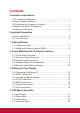
Contents Compliance Information FCC Compliance Statement................................................................. i Industry Canada Statement.................................................................. i CE Conformity for European Countries................................................ i Declaration of RoHS2 Compliance.......................................................ii Cautions and Warnings.......................................................................
4.5 Embd Player Interface................................................................. 24 4.6 Multimedia File Playback Interface.............................................. 29 5. Trouble Shooting 6. Care and Maintenance 7. Display Modes 7.1 VGA Mode................................................................................... 35 7.2 HDMI Mode................................................................................. 36 8. Specifications 9. RS-232 Protocol 9.1 Introduction...............
Copyright Information Copyright © ViewSonic Corporation, 2015. All rights reserved. Macintosh and Power Macintosh are registered trademarks of Apple Inc. Microsoft, Windows, and the Windows logo are registered trademarks of Microsoft Corporation in the United States and other countries. ViewSonic, the three birds logo, OnView, ViewMatch, and ViewMeter are registered trademarks of ViewSonic Corporation. VESA is a registered trademark of the Video Electronics Standards Association.
Product Registration To fulfill possible future product needs, and to receive additional product information as it becomes available, please visit your region section on ViewSonic’s website to register your product online. The ViewSonic CD also provides an opportunity for you to print the product registration form. Upon completion, please mail or fax to a respective ViewSonic office. To find your registration form, use the directory “:\CD\Registration”.
1. Getting Started Congratulations on your purchase of a ViewSonic® LCD display. Important! Save the original box and all packing material for future shipping needs. Note: The word “Windows” in this user guide refers to Microsoft Windows operating system. 1.1 Package Contents • • • • • • • • • • Power cable VGA cable Remote control AAA battery x 2 USB cable Audio cable Stylus pen x 3 AV cable Wall mount installation guide User manual CD wizard - User Guide - ViewBoard and ViewBoard 2.
1.2 Wall Mount Kit Specifications (VESA) Please follow the instructions in the wall mount installation guide to install your wall mount or mobile mount bracket. If attaching to other building materials, please contact your nearest dealer. inch 55 65 70 84 VESA Spec. (A x B) 400 x 400 mm 600 x 400 mm 600 x 600 mm 600 x 600 mm Standard Screw (C x D) M8 x 25 mm M8 x 60 mm M8 x 60 mm M8 x 25 mm Quantity 4 4 4 8 • ViewSonic provides the standard dimensions for wall mount kits as shown in the table above.
2. Smart Whiteboard/LCD Display Features This section introduces you to the features of your LCD Display. Note: The features or applications described in this User’s manual may vary depending on the device model purchased. 2.
2.
2.
Press to turn the display ON/OFF (Standby), or press and hold for 5 seconds to shut down Press to scroll down Enter button. Press it to select options.
2.4 Inserting Remote Control Batteries To insert the provided batteries into the remote control follow these instructions. We recommend that you don’t mix battery types. 1. Remove the cover on the rear of the remote control. 2. Insert two “AAA” batteries, ensuring the “+” symbol on the battery matches the “+” on the battery post. 3. Replace the cover by aligning it with the slot on the remote control and snapping the latch shut.
2.5 Remote Control Receiver Range The working range of the remote control receiver is shown here. It has an effective range of 8 meters. Make sure there is nothing obstructing the remote control’s signal to the receiver.
3. Setting Up Your Display Warning: For the safety of you and your unit, please do not connect to a power supply before the external device is prepared. 3.1 Connecting an External PC 1. To display video and sound from an external PC follow the instructions below. Note: External PCs can also be connected to the display via HDMI cable. • Connect a VGA cable (15-pin) from your external PC to the VGA IN port on the display.
3.2 RS232 Connections When you use a RS232 serial port cable to connect your display to an external computer, certain functions can be controlled by the PC, including power on/off, volume adjustment and more.
3.3 Connecting USB Peripherals Just like a regular PC, it is easy to connect various USB devices and other peripherals with your smart whiteboard. 1. USB Peripherals: Plug the USB device cable into the USB IN port. 2. Networking and modem cables: Plug the router cable into the LAN IN port. 3. Microphone: Plug the microphone cable into the MIC port.
3.4 AV IN Connections 1. Connect a 3-color AV cable from the AV IN ports on your display to the AV OUT ports of a peripheral device (AV cable: Yellow is Video, Red is Audio-R, White is Audio-L). 2. Plug in the power cord, and turn on the rear-panel power supply switch. 3. Press the button on the right-hand side of the display to turn the screen on. 4. Press the INPUT button to switch to the “AV” source.
3.5 HDMI Connections 1. Connect the HDMI cable to the HDMI ports on your display and peripheral device. 2. Plug in the power cord, and turn on the rear-panel power supply switch. 3. Press the button on the right-hand side of the display to turn the screen on. 4. Press the INPUT button to switch to the HDMI source. 3.6 Coaxial Connections 1. Connect a coaxial cable from DIGITAL OUT to your sound system’s coaxial connector. 2. Plug in the power cord, and turn on the rear-panel power supply switch. 3.
3.7 VGA Connections 1. To output video and sound to an external device via VGA connection: • • Connect a VGA cable (15-pin) from your display’s VGA OUT port to the input port of a projector or other device. Connect an audio cable from the AUDIO OUT port on your display to the input port of your speaker system. 2. Plug in the power cord, and turn on the rear-panel power supply switch. 3. Press the button on the right-hand side of the display to turn the screen on. 4.
4. OSD Menu Operation 4.1 Input Source To select an input source: 1. Press INPUT button on remote control to display the input setting menu, then press DOWN to enter the input source menu.. 2. Press DOWN / UP / LEFT/ RIGHT to select the input source you want. 3. Press Enter button on remote control or click with touch pen to select the input source. 4. Press EXIT key on remote control or click blank area outside menu with touch pen to quit the on-screen menu.
To adjust the brightness: 1. Press INPUT button on remote control to display the input setting menu. 2. Press RIGHT button on remote control or click “Light” icon directly with touch pen to enter Brightness Setting menu. 3. Press LEFT/ RIGHT button on remote control or drag icon directly with touch pen to adjust the value. 4. Press EXIT key on remote control or click blank area outside menu with touch pen to quit the on-screen menu.
To adjust the volume: 1. Press INPUT button on remote control to display the input setting menu. 2. Press RIGHT button on remote control or click “Volume” icon directly with touch pen to enter Brightness Setting menu. 3. Press LEFT/ RIGHT button on remote control or drag icon directly with touch pen to adjust the value. 4. Press < Mute > button on remote control or click mute icon directly with touching pen to enable or disable mute function. 5.
To adjust more functions in Embd Player mode: Press INPUT button on remote control to display the input setting menu. Press RIGHT button on remote control or click “More” icon directly with touch pen to enter More Setting menu. • • • • • • • Network access: Check the current network connection status and the network parameters of the device. Sound: Select the Sound mode and adjust the balance. Display: Adjust system wallpaper and system font size. Apps: Display all applications’ information in Embd Player.
4.2 Screen Menu In VGA mode, press MENU button on remote control to display the setting menu. Press RIGHT button on remote control under setting menu or directly click “More” icon with touch pen or press Menu directly on remote control in VGA mode to enter advanced setting menu. Press DOWN / UP / LEFT / RIGHT button on remote control or click with touch pen directly to select and adjust each option. Press EXIT key on remote control, or click blank area outside menu with touch pen to exit menu.
4.3 Picture Menu In AV, VGA and HDMI modes, press MENU button on remote control or via touch A method to display the setting menu. Press RIGHT button on remote control under setting menu or directly click “More” icon with touch pen or press Menu directly on remote control in VGA mode to enter advanced setting menu. Press DOWN / UP / LEFT / RIGHT button on remote control or click with touch pen directly to select and adjust each option.
4.4 Annotation Menu Main menu Sub menu In any input source, to place two fingers on the screen (about 20~50mm spacing) and stay more than two seconds to call up annotation menu. In this mode, user can only use touch pen to operate. Item Description Annotation menu Pop up sub-menu. Return Click to return to previous operation interface. Main Click to return to main interface of Embd Player. Pen Click to make annotation in the picture, click again to change color.
4.5 Embd Player Interface Switch to Embd Player source to display main interface as show above. Press LEFT/ RIGHT key on remote control to select icon below, and press Enter key to enter corresponding program, or click icon directly with touching pen to enter program. In any program, to press Home button on remote control or Home key on front panel of display to return to the main interface. ViewBoard Lite: Enter to ViewBoard Lite software. Folders: Enter Embd Player resource browser.
ViewBoard Lite Item Description Menu Click to pop up sub-menu. Exit Click to exit ViewBoard Lite. Picture in picture Click to pop up picture in picture interface. Image import Click to import image. Select Click to select symbols. Pen Click to write or press and hold for three seconds to set color and thickness. Eraser Click to erase symbols. Cancel Click to cancel previous step operation. Restore Click to restore cancelled operation. Page Display page number.
Folders 1. Storage device display: Click with touching pen to enter corresponding storage devices area. 2. Menu/exit menu: Click menu icon to pop up menu options. Click exit icon to exit. 3. File type menu: Office: OFFICE type files Note: Image stored by ViewBoard Lite and images stored by annotation screenshot. Video: Audio and video type files Picture: Image type files Audio: Audio type files All: All types 4.
Browser Enter web browser to surfing the internet. PIP Click picture-in-picture display interface point "4" with touching pen directly, to pop up input selection list "2", to select the input you want to display. Picture-in-picture interface operation key is shown in above figure “3”. : Click picture-in-picture input for full screen. : Click to exit picture-in-picture interface. Settings Click to setting menu.
Apps • • • • • Settings Browser Folders ViewBoard Lite Kingsoft Office 28
4.
Audio play Item Description Close the player Previous file Play/pause Next file Playlist Loop Random Single 30
Video play Item Description Close the player Previous file Fast backward Play/pause Fast forward Next file Playlist 31
5. Trouble Shooting Remote control is out of order 1. Check whether something is obstructing the display’s remote control receiver. 2. Check whether the batteries in the remote control are installed correctly. 3. Check whether the batteries need to be replaced. The unit turns of unexpect- 1. Check whether Sleep mode is enabled. edly 2. Check if there is a power outage in your area. 3. Turn on the display and see if the problem is with the signal and control system. PC mode No PC signal 1.
Video not working properly No picture / No sound 1. Check POWER status. 2. Check the signal cable. Picture trembling Poor picture 3. Check that the internal PC is installed correctly. 1. Check the signal cable. 2. Check if other electronics are interrupting the signal. 1. Adjust chroma, brightness and contrast settings in the menu. 2. Check the signal cable. Audio not working properly No sound 1. Press the Mute/ Unmute button. 2. Adjust the volume. One speaker only 3. Check the audio cable. 1.
6. Care and Maintenance Please follow these cleaning guidelines to make sure your smart whiteboard display looks like new for years to come: • Don't clean the machine if it has been turned on for a long period of time. • Unplug the unit from the wall outlet before cleaning or polishing it. • Don’t use liquid cleaners or aerosol cleaners on the screen. • Only use a slightly dampened cloth when cleaning the exterior of the unit. • Don't use system continuously for long periods of time.
7. Display Modes 7.
7.
8. Specifications Model LCD Screen Size SWB5560 CDE5560 SWB6560 CDE6560 SWB7060 CDE7060 SWB8451 CDE8451 54.6” 64.5” 69.
9. RS-232 Protocol 9.1 Introduction This document describes the hardware interface spec and software protocols of RS232 interface communication between ViewSonic Commercial TV / Digital Signage and PC or other control unit with RS232 protocol. The protocol contains three sections command: • Set-Function • Get-Function • Remote control pass-through mode ※ In the document below, “PC” represents all the control units that can sent or receive the RS232 protocol command. 9.2 Description 9.2.
9.2.2 Communication Setting - Baud Rate Select: - Data bits: - Parity: - Stop Bits: 9600bps (fixed) 8 bits (fixed) None (fixed) 1 (fixed) 9.2.3 Command Message Reference PC sends to Monitor command packet followed by “CR”. Every time PC sends control command to the Monitor, the Monitor shall respond as follows: 1. If the message is received correctly it will send “+” (02Bh) followed by “CR” (00Dh) 2. If the message is received incorrectly it will send “-” (02Dh) followed by “CR” (00Dh) 9.3 Protocol 9.3.
Set-Function format Send: (Command Type=”s”) Name Length Byte Count Bytes order ID Command Command Value1 Value2 Value3 CR Type 1 Byte 2 Byte 1 Byte 1 Byte 1 Byte 1 Byte 1 Byte 1 Byte 1 2~3 4 5 6 7 8 9 NOTE: For VT2405LED-1 and VT3205LED, the set “Power on” command is the exception. Reply: (Command Type=”+” or “-”) Name Length ID 2 Byte Command Type 1 Byte Byte Count Bytes order 1 Byte 1 CR 1 Byte 2~3 4 5 NOTE: 1.
Reply (Hex Format) Name Length ID Hex 0x34 0x30 0x32 Command Type 0x2D CR 0x0D Set-function table Set Function Length ID Command Type (ASCII) Command Value Range Comments Code (ASCII) Code (Hex) (Three ASCII bytes) Power on/ off (standby) 8 s ! 21 000: STBY 001: ON Exclude VT2405-1, and VT3205 Input Select 8 s “ 22 000: TV 001: AV 002: S-Video 003: YPbPr 004: HDMI 014: HDMI2 024: HDMI3 034: HDMI4 005: DVI 006: VGA1 016: VGA2 026: VGA3 007: OPS 017: Embd Player 008: Internal memo
Power lock 8 s 4 34 000: Unlock 001: Lock Volume 8 s 5 35 000 ~ 100 900: V olume down (-1) 901: V olume up (+1) Mute 8 s 6 36 000: OFF 001: ON (mute) Off Timer 8 s 7 37 000: OFF 001~024 (hour) PIP-Mode 8 s 9 39 000: OFF 001: PIP 002: PBP (for DS) PIP-Sound select 8 s : 3A 000: Main 001: PIP (for DS) PIP-Position 8 s ; 3B 000: Up 001: Down 002: Left 003: Right (for DS) PIP-Input 8 s < 3C 000: TV 001: AV 002: S-Video 003: YPbPr 004: HDMI 014: HDMI2 024: HD
Remote Control 8 s B 42 000: Disable 001: Enable 002: Pass through Disable: RCU has no effect on HDTV. Enabled: RCU controls the HDTV. This is the power up default on the HDTV. Pass through: RCU has no effect on HDTV and all RCU command codes are transmitted to FC via the RS232 port.
POWER Lock 1. L ock “POWER” key on the front and RCU. 2. T he SET_POWER on/off should be workable via RS232, but does not mean the POWER lock will be released under this case. 3. C an not be unlocked by reset in OSD setting. 4. W ill auto AC power-on in power-lock 5. U nder power-lock, the set will not enter power saving when no PC signal and neither not turn off when no other video signals after 15min. Remote control Lock the RCU keys, but keep the front panel buttons workable. disable 2.
9.3.2 Get-Function Listing The PC can interrogate the TV/DS for specific information. The Get-Function packet format consists of 9 bytes which is similar to the Set-Function packet structure. Note that the “Value” byte is always = 000 Get-Function description: Length: Total Byte of Message excluding “CR”. TV/DS ID Identification for each of TV/DS (01~98; default is 01).
If the Command is Not valid, Command Type=”-“ Name Length Byte Count Bytes order Command Type 1 Byte 2 Byte 1 Byte 1 ID 2~3 CR 1 Byte 4 5 Example1: Get Brightness from TV-05 and this command is valid. The Brightness value is 67.
Get-Function table Get Function Length ID Command Type (ASCII) Command Response Range Comments Code (ASCII) Code (Hex) (Three ASCII bytes) Get-Contrast 8 g a 61 000 ~ 100 GetBrightness 8 g b 62 000 ~ 100 GetSharpness 8 g c 63 000 ~ 100 Get-Color 8 g d 64 000 ~ 100 Get-Tint 8 g e 65 000 ~ 100 Get-Volume 8 g f 66 000 ~ 100 Get-Mute 8 g g 67 000: Off 001: On (muted) Get-Input select 8 g j 6A 000~ See Set-function table Get-Power status: ON/ STBY 8 g l
NOTE: 1. Time log data is replied as 6 sequential strings in following order. #1: Previous power-on date (month/ day) #2: Previous power-on time (hour/ min) #3: Previous power-off date (month/ day) #4: Previous power-off time (hour/ min) #5: Last power-on date (month/day) #6: Last power-on time (hour/ min) 2.
3. Time log data example Assumed the power-on/off record of display#01 as below 2014-8/31 08:00 On 2014-8/31 22:00 Off 2014-9/1 10:30 On 2014-9/1 11:00 To send “GET-Time log” command Send: 0x 38 30 31 67 31 30 30 30 0D Reply: #1 0x 38 30 31 72 31 31 28 51 0D #2 0x 38 30 31 72 31 31 28 20 0D #3 0x 38 30 31 72 31 30 28 51 0D #4 0x 38 30 31 72 31 30 42 20 0D #5 0x 38 30 31 72 31 31 29 21 0D #6 0x 38 30 31 72 31 31 20 50 0D (On 8/31) (On 08:00) (Off 8/31) (Off 22:00) (On 9/1) (On 10:30) 9.3.
5 05 6 06 7 07 8 08 9 09 0 0A - 0B RECALL (LAST) 0C INFO (DISPLAY) 0D 0E ASPECT (ZOOM, SIZE) 0F VOLUME UP (+) 10 VOLUME DOWN (-) 11 MUTE 12 CHANNEL/PAGE UP (+)/ BRIGHTNESS+ 13 CHANNEL/PAGE DOWN (-)/ BRIGHTNESS- 14 POWER 15 SOURCES (INPUTS) 16 17 18 SLEEP 19 MENU 1A UP 1B DOWN 1C LEFT (-) 1D RIGHT (+) 1E OK (ENTER, SET) 1F EXIT 20 21 22 23 24 25 26 27 28 29 2A 2B RED ■ (F1) 2C GREEN ■ (F2) 2D YELLOW ■ (F3) 2E BLUE ■ (F4) 2F 50
NOTE: 1. This IR-pass-through code is different from the RCU key code. 2. Special control sequence for POWER key under IR-pass through mode. 2-1. When TV/DS is OFF and receives the IR POWER code: TV/DS will turn itself on, then forward the POWER code to the host via RS232. 2-2. When TV/DS is ON and receives the IR POWER code: TV/DS will forward the POWER code to the host via RS232, then turn off itself. 2-3. When SET-POWER LOCK is enabled, the TV/DS will not respond to POWER key pressing. 3.
Other Information Customer Support For technical support or product service, see the table below or contact your reseller. NOTE: You will need the product serial number. Country/Region Website T= Telephone C = CHAT ONLINE Email Australia New Zealand www.viewsonic.com.au AUS= 1800 880 818 NZ= 0800 008 822 service@au.viewsonic.com Canada www.viewsonic.com T (Toll-Free)= 1-866-463-4775 T (Toll)= 1-424-233-2533 service.ca@viewsonic.com Europe www.viewsoniceurope.com www.viewsoniceurope.
Limited Warranty ViewSonic® Smart White Board What the warranty covers: ViewSonic warrants its products to be free from defects in material and workmanship, under normal use, during the warranty period. If a product proves to be defective in material or workmanship during the warranty period, ViewSonic will, at its sole option, repair or replace the product with a like product. Replacement product or parts may include remanufactured or refurbished parts or components.
Exclusion of damages: ViewSonic's liability is limited to the cost of repair or replacement of the product. ViewSonic shall not be liable for: 1. Damage to other property caused by any defects in the product, damages based upon inconvenience, loss of use of the product, loss of time, loss of profits, loss of business opportunity, loss of goodwill, interference with business relationships, or other commercial loss, even if advised of the possibility of such damages. 2.
Mexico Limited Warranty ViewSonic® Smart White Board What the warranty covers: ViewSonic warrants its products to be free from defects in material and workmanship, under normal use, during the warranty period. If a product proves to be defective in material or workmanship during the warranty period, ViewSonic will, at its sole option, repair or replace the product with a like product. Replacement product or parts may include remanufactured or refurbished parts or components & accessories.
Contact Information for Sales & Authorized Service (Centro Autorizado de Servicio) within Mexico: Name, address, of manufacturer and importers: México, Av. de la Palma #8 Piso 2 Despacho 203, Corporativo Interpalmas, Col. San Fernando Huixquilucan, Estado de México Tel: (55) 3605-1099 http://www.viewsonic.com/la/soporte/index.htm NÚMERO GRATIS DE ASISTENCIA TÉCNICA PARA TODO MÉXICO: 001.866.823.2004 Hermosillo: Distribuciones y Servicios Computacionales SA de CV. Calle Juarez 284 local 2 Col. Bugambilias C.