vController User Guide For SW version v2.0.1.
Thank you for choosing ViewSonic As a world leading provider of visual solutions, ViewSonic is dedicated to exceeding the world’s expectations for technological evolution, innovation, and simplicity. At ViewSonic, we believe that our products have the potential to make a positive impact in the world, and we are confident that the ViewSonic product you have chosen will serve you well.
Contents 1. Hardware settings....................................................................... 1 1.1 RS232C connections................................................................................. 1 1.2 Software installation................................................................................. 1 2. User interface.............................................................................. 2 2.1 Start Up...................................................................................
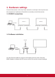
1. Hardware settings Connect the monitor to the local area network or serial port. You may then use the computer to implement vController to remotely control the monitor. 1.1 RS232C connections Monitor 1 Monitor 2 [RS-232C] PC [RS-232C Input] [RS-232C Output] [RS-232C Input] [RS-232C Output] 1.2 Software installation Internet [RJ-45] ROUTER [RJ-45] PC Use the Ethernet cable to connect to this display via the router.
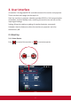
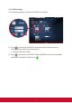
2. User interface vController 2.0 integrated RS232 and LAN command for monitor and projector. There are three main pages on the top of UI: Start Up: monitor or projector selection provides RS232 or LAN communication connection, monitor identity code, switching the machine on and off, and the input signal settings. Setting: Allows the setting or getting of monitor/projector commands. Schedule: Used to determine when the monitors or projector are to be switched on /off. 2.1 Start Up 2.1.
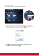
2.1.2 RS232 settings Use the following steps to perform the RS232 connection. 1 2 1. Press to search for the RS232 connection ports and then select a corresponding hardware connection port. • Default baud rate is 9600. 2. Press to connect to the RS232. When the RS232 has been successfully connected, the button will turn into .
2.1.3 Network settings Use the following steps to perform the network settings. 1 2 1. Enter the IP address of the monitor in the IP address field. When the network settings interface is opened, press the button to PING the IP address of the monitor to see if the connection is successful. • Default port number is 5000. 2. Press to connect to the network. When the network connection is successful, the button will turn into .
2.1.
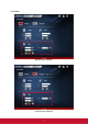
Monitor identification number (ID) Set a series of ID numbers which would be used when using the RS232C connection to control the monitor. When connected to multiple monitors, each monitor should have a unique ID. Select All to control all monitors. Note: Only monitor support identification number. ID Group Select Group and enter the ID numbers in the group field. On/Off buttons Press the button to switch the monitor on. Press the button to switch the monitor off Show that the monitor is On successful.
IP Group Press button to set the IP group. Enter the IP address of the monitor or projector in the IP address field. • Press button to add IP address into group. • Press button to remove IP address from group. • Press button to move up the focus IP address. • Press button to move down the focus IP address. • Press button to enable all IP address. • Press button to disable all IP address. • Press button to close IP group windows.
2.2. Setting 2.2.1. Setting / Getting buttons • Getting button Press the button to read the RS232 or LAN commands. If the is shown, the command would have been successfully read. If the is shown, the command was not read or the command is not supported. If the is shown, the get command was processing. • Setting the button Press the button to set the RS232 or LAN commands. If the is shown, the command would have been successfully read.
2.2.2 Monitor Setting • Setup Item Functional descriptions OSD Language Select the language for the OSD interface. Button used to activate or de-activate the power source. Button used to activate or de-activate the control panel buttons. Button used to activate or de-activate the main menu buttons. Select the digital TV channel Select the analog TV channel Choose whether to switch the remote control on /off or select the IR pass through mode.
• Picture Item Contrast Brightness Sharpness Backlight Color Tint Color mode Picture size Functional descriptions Adjust contrast to improve display quality.The black portions of the image would be blacker, while the white portions would be whiter. Adjust brightness of the image displayed Adjust and improve the image sharpness Adjust the panel backlight Use to add or decrease the color strength of the image. Use to add or decrease the tint of the image.
• Audio Sound Switch the SRS effects on or off. Write Bass Treble Increase or lower the bass volume. Increase or lower the treble volume.
• Tiling Item Tiling-Mode TilingCompensation Tiling-H by V Monitors Tiling-Position Functional descriptions This function allows users to establish a large array of monitors (TV walls). This function requires daisy chain connections. The maximum number of monitors to be arranged horizontally / vertically would depend on the specifications of the monitors used. Switch the tiling-compensation function on or off.
• KeyPad Item Functional descriptions Commands Devices supported supported Power On button Press this button to power on device. Write Several TV types Power Off button Press this button to power off device. Write All devices Menu button Press this button to access the OSD menu Write All devices Volume down button Press this button to decrease the audio output level. Write All devices Volume up button Press this button to increase the audio output level.
Press button to select the input source Write All devices Select the desired number by pressing the 0~9 buttons Write All devices Move the selection row up/down/ left/right or adjust the selected item in the OSD interface.
• Macro There are 5 group macro for user to define. 1. Group Name • Key in group name here 2. Press Edit icon to add command to Macro instruction set.
• Drop-down menu to select command. • Drop-down menu to select command data. • Press button to command into group. • Press button to remove command from group. • Press button to move up the focus command. • Press button to move down the focus command. • Press button to enable all IP address. • Press button to close macro edit. 3.
2.2.3 Projector Setting • Setup Pro 9 Series no selected Pro 9 Series selected Item Functional descriptions Commands supported Devices supported OSD Language Select the language for the OSD interface.
• Picture (Only support Pro 9 Series) Item Functional descriptions Commands supported Devices supported Contrast Adjust contrast to improve display. The black portions of the image would be blacker, while the white portions would be whiter. Write/read Support Pro 9 Series only Brightness Adjust brightness of the image displayed.
• Audio Pro 9 Series no selected Pro 9 Series selected Volume Adjust the projector volume Commands supported Write / read Mute Mute or unmute the projector speakers Write / read Item Functional descriptions 19 Devices supported All devices Supported NonPro 9 Series model
• Keypad Pro 9 Series no selected Pro 9 Series selected Item Functional descriptions Commands Devices supported supported Power On button Press this button to power on device. Write Several TV types Power Off button Press this button to power off device.
ECO mode button Write All devices LAMP mode button Press the button to cycle among ECO, Write Normal, and Dynamic ECO Support Pro9 series only Audio mode button Write All devices Write All devices Write All devices BLANK On/Off button FREEZE On/Off button Volume down button Press this button to decrease the audio output level. Write Volume up button Press this button to increase the audio output level. Write Mute button Press this button to turn the mute function on/off.
1. Move the selection row up/ down/left/right or adjust the selected item in the OSD interface. Write 2. ENTER button to confirm the action 3. MENU button access the OSD menu Supported NonPro 9 Series model Press button to select the input source. Write Supported NonPro 9 Series model Write Supported Pro 9 Series model only Write Supported Pro 9 Series model only Source switch button Move the selection row up/ down/ left/right or adjust the selected item in the OSD interface.
• Macro There are 5 group macro for user to define. 1. Group Name • Key in group name here 2. Press Edit icon to add command to Macro instruction set.
• Drop-down menu to select command. • Drop-down menu to select command data. • Press button to command into group. • Press button to remove command from group. • Press button to move up the focus command. • Press button to move down the focus command. • Press button to enable all IP address. • Press button to close macro edit. 3.
2.3 Schedule Pre-set schedules can be used to determine when the monitors are to be switched on /off. Be reminded that in order for this function to work and the monitor switched on/off according to schedule, the vController software must be kept running. • Group: Group On or Off schedule. You can select Group A to H or No group. • Name: Type a schedule name. • Protocol: Press • Device: Press for RS232 or for Dispaly or for LAN. for Projector. • COM: Set the RS232 COM port. • ID: Select display ID.
3. Command Mode Press to enter the command mode. The figure below shows the Command mode interface. Perform the following steps: • Select ASCII or Hex, and then manually enter the Command.
4. Language Press the button to select the language.
5. About Press the button to monitor the software version and copyright notice.
6. Other Information Customer Support For technical support or product service, see the table below or contact your reseller. NOTE: You will need to provide the product serial number. Country/Region Website T= Telephone C = CHAT ONLINE Email Australia New Zealand www.viewsonic.com.au AUS= 1800 880 818 NZ= 0800 008 822 service@au.viewsonic. com Canada www.viewsonic.com T = 1-866-463-4775 service.ca@viewsonic. com Europe www.viewsoniceurope.com http://www.viewsoniceurope.
30