CDP4260-L/CDP4262-L/CDX4652-L/ CDP5560-L/CDP5562-L LCD Monitor User Guide IMPORTANT: Please read this User Guide to obtain important information on installing and using your product in a safe manner, as well as registering your product for future service. Warranty information contained in this User Guide will describe your limited coverage from ViewSonic Corporation, which is also found on our web site at http:// www.viewsonic.
Compliance Information NOTE: This section addresses all connected requirements and statements regarding regulations. Confirmed corresponding applications shall refer to nameplate labels and relevant markings on unit. FCC Statement This device complies with Part 15 of the FCC Rules. Operation is subject to the following two conditions: (1) this device may not cause harmful interference, and (2) this device must accept any interference received, including interference that may cause undesired operation.
CE Conformity for European Countries The device complies with the EMC Directive 2004/108/EC and Low Voltage Directive 2006/95/EC. Following information is only for EU-member states: The mark shown to the right is in compliance with the Waste Electrical and Electronic Equipment Directive 2002/96/EC (WEEE). The mark indicates the requirement NOT to dispose of the equipment as unsorted municipal waste, but use the return and collection systems according to local law.
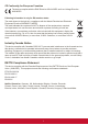
Declaration of RoHS2 Compliance This product has been designed and manufactured in compliance with Directive 2011/65/EU of the European Parliament and the Council on restriction of the use of certain hazardous substances in electrical and electronic equipment (RoHS2 Directive) and is deemed to comply with the maximum concentration values issued by the European Technical Adaptation Committee (TAC) as shown below: Substance Proposed Maximum Concentration Actual Concentration Lead (Pb) 0,1% < 0,1% Mercur
Safety Precautions FOR OPTIMUM PERFORMANCE, PLEASE NOTE THE FOLLOWING WHEN SETTING UP AND USING THE LCD COLOR MONITOR: • DO NOT REMOVE MONITOR BACK COVER. There are no user serviceable parts inside and opening or removing covers may expose you to dangerous shock hazards or other risks. Refer all servicing to qualified service personnel. • Do not spill any liquids into the cabinet or use your monitor near water.
CAUTION: Immediately unplug your monitor from the wall outlet and refer servicing to qualified service personnel under the following conditions: • When the power supply cord or plug is damaged. • If liquid has been spilled, or objects have fallen into the monitor. • If the monitor has been exposed to rain or water. • If the monitor has been dropped or the cabinet damaged. • If the monitor does not operate normally by following operating instructions.
Table Of Contents 1. Unpacking and Installation....................1 1.1. Unpacking........................................1 1.2. Package Contents............................1 1.3. Installation Notes..............................1 1.4. Installing and Removing Table Stands (optional)..............................2 1.5. Mounting on a Wall...........................2 1.5.1. VESA Grid..............................3 2. Parts and Functions...............................4 2.1. Control Panel.....................
Copyright Information Copyright © ViewSonic® Corporation, 2013. All rights reserved. ViewSonic©, the three birds logo, OnView, ViewMatch, and ViewMeter are registered trademarks of ViewSonic Corporation. ENERGY STAR® is a registered trademark of the U.S. Environmental Protection Agency (EPA). As an ENERGY STAR® partner, ViewSonic Corporation has determined that this product meetsthe ENERGY STAR® guidelines for energy efficiency.
1. Unpacking and Installation 1.1. Unpacking • • • • This product is packed in a carton, together with the standard accessories. Any other optional accessories will be packed separately. Due to the size and weight of this display it is recommended for two people to move it. After opening the carton, ensure that the contents are complete and in good condition. 1.2.
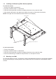
1.4. Installing and Removing Table Stands (optional) To install table stands: 1. 2. 3. 4. Ensure your display is powered off. Spread a protective sheet on a flat surface. Grab the carrying handles and place the display face-down on the protective sheet. After inserting the stand in the guide block, tighten the screws on both sides of the display. NOTE: The longer side of the stand should face the front of the display.
Protective Sheet VESA Grid Table For Tabletop stand 1. Lay a protective sheet on a table, which was wrapped around the display when it was packaged, beneath the screen surface so as not to scratch the screen face. 2. Ensure you have all accessories for mounting this display (wall mount, ceiling mount, table stand, etc). 3. Follow the instructions that come with the base mounting kit. Failure to follow correct mounting procedures could result in damage to the equipment or injury to the user or installer.
2. Parts and Functions 2.1.
1 POWER button Use this button to turn the display on or put the display to standby. 2 MUTE button Switch the audio mute ON/OFF. 3 INPUT button Use this button to select the input source. 4 [ ] button Increase the adjustment while OSD menu is on, or increase the audio output level while OSD menu is off. • Used as [SET] button in the On-Screen-Display menu. 5 [ ] button Decrease the adjustment while OSD menu is on, or decrease the audio output level while OSD menu is off.
2.2.
1 AC IN AC power input from the wall outlet. 10 DVI IN DVI-D video input. 2 MAIN POWER SWITCH Switch the main power on/off. 11 DVI OUT / VGA OUT DVI or VGA video output. 3 IR IN / 4 IR OUT (3.5 mm) IR signal output/input for the loop-through function. NOTES: • This display’s remote control sensor will stop working if the jack [IR IN] is connected. • To remotely control your A/V device via this display, refer to page 14 for IR Pass Through connection. 12 VGA IN (D-Sub) VGA video input.
2.3. Remote Control 5 2.3.1. General functions 6 POWER 1 10 VIDEO SOURCE SMART 7 AUDIO SOURCE 2 11 8 12 PIP 3 ON/OFF INPUT 9 CHANGE 4 13 CONTRAST BRIGHTNESS 5 DISPLAY 6 10 14 15 MENU 16 SET 7 8 11 17 AUTO ADJUST EXIT VOL UP 18 19 20 9 12 VOL DOWN 21 22 OPTION 13 23 14 1 2 3 4 15 [POWER] button Press to switch on the display from standby mode. Press again to turn it off and back into standby mode. [SMART] button Press to activate Smart Menu.
2.3.2. Inserting the batteries in the remote control The remote control is powered by two 1.5V AAA batteries. To install or replace batteries: 1. Press and then slide the cover to open it. 2. Align the batteries according to the (+) and (–) indications inside the battery compartment. 3. Replace the cover. 2.3.4. Operating range of the remote control Point the top of the remote control toward the display’s remote control sensor when pressing a button.
3. Connecting External Equipment 3.1. Connecting External Equipment (DVD/VCR/VCD) 3.1.1. Using COMPONENT video input Audio Out COMPONENT Out (YPbPr) [R] [L] DVD / VCR / VCD [AUDIO IN] [COMPONENT IN] (Pr/Pb/Y) 3.1.2.
3.2. Connecting a PC 3.2.1. Using VGA input VGA Out D-Sub 15 pin PC [R] Audio Out [L] [AUDIO IN] [VGA IN] [VGA AUDIO IN] 3.2.2. Using DVI input DVI Out PC [R] Audio Out [L] [AUDIO IN] [DVI IN] [VGA AUDIO IN] 3.2.3.
3.3. Connecting Audio Equipment 3.3.1. Connecting external speakers External speakers 3.3.2.
3.4. Connecting Multiple Displays in a Daisy-chain Configuration You can interconnect multiple displays to create a daisy-chain configuration for applications such as a video wall. NOTE: Maximum 25 displays (5x5) can be used in a daisy-chain configuration. 3.4.1. Display control connection Connect the [RS232C OUT] connector of DISPLAY 1 to the [RS232C IN] connector of DISPLAY 2. PC [RS-232C] DISPLAY 1 [RS-232C IN] DISPLAY 2 [RS-232C OUT] [RS-232C IN] 3.4.2.
3.4.4. IR connection (optional) DISPLAY 1 External IR Receiver [IR IN] DISPLAY 2 [IR OUT] [IR IN] POWER VIDEO SOURCE SMART AUDIO SOURCE PIP ON/OFF INPUT CONTRAST CHANGE BRIGHTNESS DISPLAY MENU SET AUTO ADJUST EXIT VOL UP VOL DOWN OPTION NOTE: This display’s remote control sensor will stop working if the [IR IN] is connected. 3.5.
4. OSD Menu 4.2. An overall view of the On-Screen Display (OSD) structure is shown below. You can use it as a reference for further adjusting your display. 4.1. OSD Menu Overview 4.2.1. PICTURE menu PICTURE Navigating the OSD Menu 4.1.1.
USER COLOR With this function you can adjust the color tones of the image precisely by changing the R (Red), G (Green) and B (Blue) settings independently. NOTE: This item is functional only when {COLOR TEMPERATURE} is set to {USER}. 4.2.2. SCREEN menu SCREEN GAMMA SELECTION Gamma is what controls the overall brightness of an image.
NORMAL INPUT RESOLUTION Set the resolution of the VGA input. This is only required when the display is unable to detect the VGA input resolution correctly. NOTE: This item is functional for VGA input only. The options are: • {1024x768 / 1280x768 / 1360x768} • {1400x1050 / 1680x1050} • {1600x1200 / 1920x1200} • {Auto}: Determines the resolution automatically. The selected settings will become effective after turning off the power and turn it on again.
4.2.4.
4. For more schedule settings, press [EXIT] button and then repeat the steps above. A check mark in the box next to the number of the schedule item indicates that the selected schedule is in effect. • The time for the display to turn on and turn off. • The days in a week for the display to activate. • Which input source the display will use for each scheduled activation period. NOTE: You should set up current date and time in {DATE AND TIME} menu before using this function. 1.
4.2.6. CONFIGURATION2 menu 1 2 PIP CONFIGURATION2 LANGUAGE OSD TURN OFF OSD H POSITION OSD V POSITION INFORMATION OSD MONITOR INFORMATION MONITOR ID IR CONTROL TILING POWER ON DELAY CLOSED CAPTION CONFIGURATION2 RESET OFF • {NORMAL} - All displays can be operated normally by the remote control. • {LOCK} - Lock the remote control function of this display. To unlock, press and hold the [DISPLAY] button on the remote control for 5 (five) seconds. 45 50 50 3 SEC.
4.2.7. CONFIGURATION3 menu • POSITION - Select the position of this display in the screen matrix. • FRAME COMP. - Choose to turn the frame compensation function on or off. If turned on, the display will adjust the image to compensate for the width of the display bezels in order to accurately display the image. • ENABLE: Choose to enable or disable the Tiling function. If enabled, the display will apply the settings in {H MONITORS}, {V MONITORS}, {POSITION}, and {FRAME COMP.}.
SCREEN SAVER Choose to enable the panel saving functions to reduce the risk of the “image persistence”. 4.2.8. ADVANCED OPTION menu SCREEN SAVER COOLING FAN BRIGHTNESS MOTION AUTO OFF OFF 1 PIP 2 :SEL +-:ADJ EXIT :RETURN MENU :EXIT MENU ADVANCED OPTION INPUT CHANGE TERMINAL SETTING SCAN CONVERSION COLOR SYSTEM SCAN MODE SERIAL CONTROL LAN SETTING APM ADVANCED OPTION RESET FACTORY RESET NORMAL LAN OFF 3 • {COOLING FAN} - Select {ON} to turn on the cooling fan all the time.
SCAN CONVERSION Choose to enable or disable the IP (Interlace to Progressive) conversion function. • {PROGRESSIVE} - Enable the IP conversion function (recommended). Once enabled, the interlace input signal will be converted to progressive format for better display quality. • {INTERLACE} - Disable the IP function. This mode is suitable for displaying motion pictures, but it increases the chance of image retention. • DHCP - Choose to enable or disable the DHCP function.
5. Input Mode VGA Resolution: Active Resolution H Pixels V Lines 480 640 480 480 Refresh Rate Pixel Rate Aspect Ratio Stand for Mode 60 Hz 72 Hz 75 Hz 25.175 MHz 31.5 MHz 31.5 MHz 4:3 Video Graphic Array WVGA 720 400 70 Hz 33.75 MHz 16:9 SVGA 800 WXGA WXGA SXGA SXGA WXGA WXGA UXGA HD1080 1280 1280 1280 1280 1360 1366 1600 1920 40 MHz 49.5 MHz 65 MHz 78.75 MHz 79.5 MHz 79.5 MHz 108 MHz 108 MHz 85.5 MHz 85.5 MHz 162 MHz 148.
6. Cleaning and Troubleshooting 6.1. Cleaning When Using the Display • Do not bring your hands, face or objects close to the ventilation holes of the display. The top of the display is usually very hot due to the high temperature of exhaust air being released through the ventilation holes. Burns or personal injuries may occur if any body parts are brought too close. Placing any object near the top of the display could also result in heat related damage to the object as well as the display itself.
6.2. Troubleshooting Symptom Possible Cause Remedy No picture is displayed 1. The power cord is disconnected. 1. Plug in the power cord. 2. The main power switch on 2. Make sure the power switch is the back of the display is not switched on. switched on. 3. Connect a signal connection to 3. The selected input has no the display. connection. 4. The display is in standby mode.
7. Technical Specifications 7.1. CDP4260-L / CDP4262-L Display: Item Specifications Screen Size (Active Area) 42” LCD Aspect Ratio 16:9 Number of pixels 1920 (H) x 1080 (V) Pixel pitch 0.4845 (H) x 0.4845 (V) [mm] Displayable colors 1.
General: Item Specifications Power Supply AC 100 ~ 240V, 50 ~ 60Hz Power Consumption (Max) 150W Power Consumption (typ.) 120W Power Consumption (Standby & Off) <0.5W (RS232 in active) Dimensions (With Stand) [W x H x D] 965.8 x 601.4 x 400 mm Dimensions (Without Stand) [W x H x D] 965.8 x 558.8 x 69 mm Weight (With Stand) 20.6 Kg Weight (Without Stand) 18.3 Kg Gross Weight (Without Stand) 24.
7.2. CDX4652-L Display: Item Specifications Screen Size (Active Area) 46” LCD Aspect Ratio 16:9 Number of pixels 1920 (H) x 1080 (V) Pixel pitch 0.17675 (H) x 0.53025 (V) [mm] Displayable colors 16.
General: Item Specifications Power Supply AC 100 ~ 240V, 50 ~ 60Hz Power Consumption (Max) 200W Power Consumption (typ.) 120W Power Consumption (Standby & Off) <0.5W (RS232 in active) Dimensions (With Stand) [W x H x D] 1023.98 x 629.41 x 400 mm Dimensions (Without Stand) [W x H x D] 1023.98 x 578.57 x 125.7 mm Weight (With Stand) 25.3 Kg Weight (Without Stand) 23 Kg Gross Weight (Without Stand) 31.
7.3. CDP5560-L / CDP5562-L Display: Item Specifications Screen Size (Active Area) 55” LCD Aspect Ratio 16:9 Number of pixels 1920 (H) x 1080 (V) Pixel pitch 0.63 (H) x 0.63 (V) [mm] Displayable colors 1.
General: Item Specifications Power Supply AC 100 ~ 240V, 50 ~ 60Hz Power Consumption (Max) 190W Power Consumption (typ.) 130W Power Consumption (Standby & Off) <0.5W (RS232 in active) Dimensions (With Stand) [W x H x D] 1247 x 758.2 x 400 mm Dimensions (Without Stand) [W x H x D] 1247 x 717.8 x 70 mm Weight (With Stand) 32.6 Kg Weight (Without Stand) 30.3 Kg Gross Weight (Without Stand) 37.
8. Other Information Customer Support For technical support or product service, see the table below or contact your reseller. NOTE: You will need the product serial number. Country/Region Website T = Telephone F = FAX Email Australia New Zealand www.viewsonic.com.au AUS= 1800 880 818 NZ= 0800 008 822 service@au.viewsonic.com Canada www.viewsonic.com T (Toll-Free)= 1-866-463-4775 T (Toll)= 1-424-233-2533 F= 1-909-468-3757 service.ca@viewsonic.com Europe www.viewsoniceurope.com www.
Limited Warranty ViewSonic® LCD Commercial Display What the warranty covers: ViewSonic warrants its products to be free from defects in material and workmanship, under normal use, during the warranty period. If a product proves to be defective in material or workmanship during the warranty period, ViewSonic will, at its sole option, repair or replace the product with a like product. Replacement product or parts may include remanufactured or refurbished parts or components.
Limitation of implied warranties: There are no warranties, express or implied, which extend beyond the description contained herein including the implied warranty of merchantability and fitness for a particular purpose. Exclusion of damages: ViewSonic’s liability is limited to the cost of repair or replacement of the product. ViewSonic shall not be liable for: 1.
Mexico Limited Warranty ViewSonic® LCD Commercial Display What the warranty covers: ViewSonic warrants its products to be free from defects in material and workmanship, under normal use, during the warranty period. If a product proves to be defective in material or workmanship during the warranty period, ViewSonic will, at its sole option, repair or replace the product with a like product. Replacement product or parts may include remanufactured or refurbished parts or components.
Contact Information for Sales & Authorized Service (Centro Autorizado de Servicio) within Mexico: Name, address, of manufacturer and importers: México, Av. de la Palma #8 Piso 2 Despacho 203, Corporativo Interpalmas, Col. San Fernando Huixquilucan, Estado de México Tel: (55) 3605-1099 http://www.viewsonic.com/la/soporte/index.htm NÚMERO GRATIS DE ASISTENCIA TÉCNICA PARA TODO MÉXICO: 001.866.823.2004 Hermosillo: Distribuciones y Servicios Computacionales SA de CV. Calle Juarez 284 local 2 Col. Bugambilias C.