CDP3235 CDP4235 CDP4235-T CDP4635 CDP4635-T CDX5550-L User Guide IMPORTANT: Please read this User Guide to obtain important information on installing and using your product in a safe manner, as well as registering your product for future service. Warranty information contained in this User Guide will describe your limited coverage from ViewSonic Corporation, which is also found on our web site at http:// www.viewsonic.
Compliance Information For U.S.A. This device complies with part 15 of FCC Rules. Operation is subject to the following two conditions: (1) this device may not cause harmful interference, and (2) this device must accept any interference received, including interference that may cause undesired operation. This equipment has been tested and found to comply with the limits for a Class B digital device, pursuant to part 15 of the FCC Rules.
Important Safety Instructions 1. Read these instructions completely before using the equipment. 2. Keep these instructions in a safe place. 3. Heed all warnings. 4. Follow all instructions. 5. Do not use this equipment near water. Warning: To reduce the risk of fire or electric shock, do not expose this apparatus to rain or moisture. 6. Do not block any ventilation openings. Install the equipment in accordance with the manufacturer’s instructions. 7.
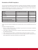
Declaration of RoHS Compliance This product has been designed and manufactured in compliance with Directive 2002/95/EC of the European Parliament and the Council on restriction of the use of certain hazardous substances in electrical and electronic equipment (RoHS Directive) and is deemed to comply with the maximum concentration values issued by the European Technical Adaptation Committee (TAC) as shown below: Substance Proposed Maximum Concentration Actual Concentration Lead (Pb) 0,1% < 0,1% Mercury
Copyright Information Copyright © ViewSonic® Corporation, 2012. All rights reserved. ViewSonic®, the three birds logo, OnView®, ViewMatch™, and ViewMeter® are registered trademarks of ViewSonic® Corporation. ENERGY STAR® is a registered trademark of the U.S. Environmental Protection Agency (EPA). As an ENERGY STAR® partner, ViewSonic Corporation has determined that this product meetsthe ENERGY STAR® guidelines for energy efficiency.
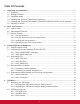
Table Of Contents 1. Unpacking and Installation.............................................................................................................1 1.1. Unpacking.................................................................................................................................1 1.2. Package Contents.....................................................................................................................1 1.3. Installation Notes.............................................
4.2.4. 4.2.5. 4.2.6. 4.2.7. 4.2.8. PIP menu......................................................................................................................17 CONFIGURATION1 menu............................................................................................18 CONFIGURATION2 menu............................................................................................19 CONFIGURATION3 menu............................................................................................
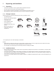
1. Unpacking and Installation 1.1. Unpacking • This product is packed in a carton, together with the standard accessories. • Any other optional accessories will be packed separately. • Due to the size and weight of this display it is recommended for two people to move it. • After opening the carton, ensure that the content is in good condition and complete. 1.2.
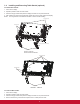
1.4. Installing and Removing Table Stands (optional) To install table stands: 1. Power off the display. 2. Spread a protective sheet on a flat surface. 3. Grab the carrying handles and place the display face-down on the protective sheet. 4. After inserting the stand in the guide block, tighten the screws on both sides of the display. NOTE: The long-end side of the stand should face to the front while installing.
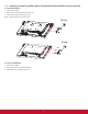
1.5. Installing and Removing OPS module (CDP4235/CDP4635/CDX5550-L series) (optional) To install OPS Module: 1. Power off the display. 2. Remove the cover of OPS after take screw off. 3. Insert OPS module and then fix by screw. NOTE: Keep the OPS cover for future use. Screw Screw OPS To remove OPS Module: 1. Power off the display. 2. Remove screw and plug out OPS module. 3. Install OPS cover and then fix by screw.
1.6. Mounting on a Wall To mount this display to a wall, you will have to obtain a standard wall-mounting kit (commercially available). We recommend using a mounting interface that complies with TUV-GS and/or UL1678 standard in North America. 100 200 100 400 Protective Sheet Protective Sheet 400 200 Table CDP3235/CDP4235/CDP4635 series Table Tabletop stand Tabletop stand CDX5550-L 1.
2. Parts and Functions 2.1. Control Panel 9 9 MUTE INPUT MENU 10 MENU 10 1 2 3 4 5 6 7 8 1 CDP3235/CDP4235/CDP4635 series 1 POWER button 8 4 5 INPUT button Use this button to select the input source. • When the On Screen Display menu is active, this is also used as the [SET] button. 9 [ ] button 7 8 MENU button Remote control sensor and power status indicator • Receives command signals from the remote control.
2.2. Input/Output Terminals CDP4235/CDP4635 series CDP3235 15 CDX5550-L 15 15 CDP3235 (OUT) (OUT) Pr Pb Y 1 3 2 (IN) 1 2 (IN) 3 4 5 6 7 8 9 10 11 12 10 13 14 CDP4235/CDP4635/CDX5550-L series (OUT) (OUT) Pr Pb Y 1 3 2 (IN) 2 1 2 1 3 (IN) 4 5 6 7 MAIN POWER SWITCH 8 16 9 10 • AUDIO IN 1: 3.5mm stereo phone jack • AUDIO IN 2, 3: RCA phone jack 11 RS232C (OUT/IN) RJ-45 VGA OUT (D-Sub) 12 Output the VGA signal from the VGA IN (D-Sub).
2.3. Remote Control 5 2.3.1. General functions 6 POWER 1 10 SMART VIDEO SOURCE AUDIO SOURCE 2 7 11 12 8 13 BRIGHTNESS 5 DISPLAY 6 9 14 15 10 Press to move the sub-picture left in PIP mode. [SET] button [AUTO ADJUST] button 7 8 17 EXIT VOL UP MUTE [MUTE] button [VIDEO SOURCE] button Press to toggle Video Source Menu. Press [ ] or [ ] button to select one of the video sources among HDMI, DVI-D, VGA, DVD / HD, VIDEO-S, or VIDEO . Press [SET] button to confirm and exit.
2.3.2. Inserting the batteries in the remote control 2.3.4. Operating range of the remote control Point the top of the remote control toward the display’s remote control sensor when pressing a button. The remote control is powered by two 1.5V AAA batteries. Use the remote control within a distance of less than 10m/33ft from the display’s sensor, and a horizontal and vertical angle of less than 30 degrees.
3. Connecting External Equipment 3.1. Using the Switch Cover A cover for the power switch is provided to prevent the display from being turned on or off accidentally. To lock the cover into position: 1. Align and insert the cover to the indentation located beside the main switch. 2. Use the screw to lock the cover.
3.2. Connecting External Equipment (DVD/VCR/VCD) 3.2.1. Using COMPONENT video input COMPONENT (YPbPr) Audio Output DVD / VCR / VCD To [AUDIO IN 2, 3] COMPONENT (YPbPr) 3.2.2.
3.3. Connecting a PC 3.3.1. Using VGA input From analog VGA output Mini D-Sub 15 pin From audio output PC or IBM compatible To [AUDIO IN 1, 2, 3] To [VGA IN] 3.3.2.
3.3.3. Using HDMI input From HDMI output PC or IBM compatible To [HDMI IN] 3.3.4. CONNECTING THE TOUCH MODULE There are two ways to connect the touch module. 1. Connect the USB cable on the display to a PC. The touch module supports easy Plug-and-Play operations. There is no need to install additional drivers on the PC. 2. Install an OPS (Open Pluggable Specification) module in to the slot on the rear of the display. Refer to the module’s documentation for user instructions.
3.4. External Audio Connection 3.4.1. Connecting external speakers External speaker 3.4.2.
3.5. Connecting Multiple Displays in a Daisy-chain Configuration You can interconnect multiple displays to create a daisy-chain configuration for applications such as a video wall. NOTE: Maximum 9 displays can be used in a daisy-chain configuration. 3.5.1. Video connection Connect one of the following: • Connect the [RS232C OUT] connector of display 1 to the [RS232C IN] connector of display 2. • Connect the [VGA OUT] connector of display 1 to the [VGA IN] connector of display 2.
4. OSD Menu 4.2. An overall view of the On-Screen Display (OSD) structure is shown below. You can use it as a reference for further adjusting your display. 4.1. OSD Menu Overview 4.2.1. PICTURE menu PICTURE Navigating the OSD Menu 4.1.1.
GAMMA SELECTION V POSITION Gamma is what controls the overall brightness of an image. Images which are not corrected properly can appear too white or too dark, so controlling the gamma properly can have a huge influence on the overall picture quality of your display. Press the [ ] button to move the image up, or [ ] to move the image down. CLOCK Adjust the width of the image. The options are: {NATIVE} / {2.2} / {2.4} / {S GAMMA}. NOTE: This item is functional for VGA input only.
4.2.4. PIP menu V ZOOM Expands the vertical size of the image only. PIP PIP MODE PIP SIZE PIP AUDIO PIP H POSITION PIP V POSITION SUB INPUT PIP RESET H POSITION Moves the horizontal position of the image left or right. PIP V POSITION Moves the vertical position of the image up or down. OFF SMALL MAIN AUDIO 100 0 VIDEO 1 2 3 INPUT RESOLUTION Set the resolution of the VGA input. This is only required when the display is unable to detect the VGA input resolution correctly.
By pressing the [PIP ON/OFF] button on the remote control, you can change the mode in the order shown below: PIP SBS ASPECT POP SBS FULL SCHEDULE TODAY OFF 1 2 3 4 5 6 7 The resolutions in the PIP and POP modes are configured as follows: PIP SIZE {SMALL} : 320 x 240 pixels {MIDDLE} : 480 x 320 pixels {LARGE} : 640 x 480 pixels EVERY DAY WED SAT EXIT 20 : 19 : 55 INPUT _ MON THU SUN :RETURN TUE FRI EVERY WEEK MENU :EXIT MENU 2.
DATE AND TIME INFORMATION OSD Adjust the current date and time for the display’s internal clock. Set the period of time the information OSD displayed on the upper right corner of the screen. The information OSD will display when input signal is changed. DATE AND TIME YEAR MONTH DAY HOUR MINUTE DAYLIGHT SAVING TIME CURRENT DATE TIME 2011 . 08 . 04 :SEL +-:ADJ EXIT :RETURN The information OSD will remain on the screen with {OFF} selection. 2011 08 04 20 20 OFF The options are: {OFF, 3 SEC. ~ 10 SEC.
Example: 5 x 5 screen matrix (25 displays) H MONITORS = 5 displays V MONITORS = 5 displays not compliant with it, images may not be displayed correctly. CONFIGURATION2 RESET V MONITORS H MONITORS 1 2 3 4 5 6 7 8 9 10 11 12 13 14 15 16 17 18 19 20 21 22 23 24 25 Reset all settings in the CONFIGURATION2 menu to factory preset values. Position • H MONITORS - Select the number of displays on the horizontal side. • V MONITORS - Select the number of displays on the vertical side.
SCREEN SAVER TERMINAL SETTING Choose to enable the panel saving functions to reduce the risk of the “image persistence”. Select the mode to display the HDMI or DVI signal according to their signal format depending on their source device. COOLING FAN BRIGHTNESS MOTION :SEL +-:ADJ {DVI MODE}: Used for DVI-D signal. • Select {DVI-PC} when the source device is a PC. • SCREEN SAVER AUTO OFF OFF EXIT :RETURN MENU :EXIT • {HDMI SIGNAL}: Used for HDMI signal.
LAN SETTING Assign {IP ADDRESS}, {SUBNET MASK}, and {DEFAULT GATEWAY} for the display. LAN SETTING DHCP CLIENT IP ADDRESS SUBNET MASK DEFAULT GATEWAY 1 OFF PIP 2 3 :SEL • +-:ADJ EXIT :RETURN MENU :EXIT MENU DHCP - Choose to enable or disable the DHCP function. If enabled, the display will be assigned IP address, Subnet mask and Default gateway automatically. If disabled, you will be prompted to enter the following value manually. Finally, press [SET] button to store and save the chosen values.
5. Input Mode VGA Resolution: Standard Resolution VGA WVGA SVGA XGA WXGA WXGA SXGA SXGA WXGA WXGA UXGA HD1080 Active Resolution H Pixels V Lines 480 640 480 480 720 400 600 800 600 768 1024 768 1280 768 1280 800 1280 960 1280 1024 1360 768 1366 768 1600 1200 1920 1080 Refresh Rate Pixel Rate Aspect Ratio Stand for Mode 60 Hz 72 Hz 75 Hz 70 Hz 60 Hz 75 Hz 60 Hz 75 Hz 60 Hz 60 Hz 60 Hz 60 Hz 60 Hz 60 Hz 60 Hz 60 Hz 25.175 MHz 31.5 MHz 31.5 MHz 33.75 MHz 40 MHz 49.5 MHz 65 MHz 78.75 MHz 79.5 MHz 79.
6. Cleaning and Troubleshooting 6.1. Cleaning Caution When Using the Display • Do not bring your hands, face or objects close to the ventilation holes of the display. The top of the display is usually very hot due to the high temperature of exhaust air being released through the ventilation holes. Burns or personal injuries may occur if any body parts are brought too close.
6.2. Troubleshooting Symptom Possible Cause Remedy No picture is displayed 1. The power cord is disconnected. 1. Plug in the power cord. 2. The main power switch on the back of the display is not switched on. 2. Make sure the power switch is switched on. 3. The selected input has no connection. 3. Connect a signal connection to the display. 4. The display is in standby mode.
7. Technical Specifications CDP3235 Display: Item Specifications Screen Size (Active Area) 80.1cm/32”(31.5” viewable) Diagonal, 697.689mm(H), 392.256mm(V) Aspect ratio 16:9 Number of pixels 1366 (H) x 768 (V) Pixel pitch 0.51075 (H) x 0.51075 (V) [mm] Displayable colors 16.
Gross Weight 16.
CDP4235/CDP4235-T Display: Item Specifications Screen Size (Active Area) 42” LCD 106.7cm/42” Diagonal, 930.24mm(H), 523.26mm(V) Aspect ratio 16:9 Backlight CCFL Number of pixels 1920 (H) x 1080 (V) Pixel pitch 0.4845 (H) x 0.4845 (V) [mm] Displayable colors 16.
VESA Wall mount 400x200mm,200x200, M6 Gross Weight 27.5 Kg 26.
CDP4635/CDP4635-T Display: Item Specifications Screen Size (Active Area) 116.8cm/46” Diagonal , 1018.08mm(H), 572.67mm(V) Aspect ratio 16:9 Backlight CCFL Number of pixels 1920 (H) x 1080 (V) Pixel pitch 0.53025 (H) x 0.53025 (V) [mm] Displayable colors 16.
VESA Wall mount 400x400mm,400x200mm, M6 Gross Weight 31 Kg Environmental Condition: Item Temperature Humidity Altitude Specifications Operational 0 ~ 40°C Storage -20 ~ 60°C Operational 20 ~ 80% RH (No condensation) Storage 5 ~ 95% RH (No condensation) Operational 0 ~ 3,000 m Internal Speaker: Item Specifications Output 10W+10W(RMS) Impedance 8Ω Output Sound Pressure 82 dB/W/M Frequency Response 160 Hz ~ 13 KHz CDP4635-T touch specification Touch Panel Detection Method Optical tou
CDX5550-L Display: Item Specifications Screen Size (Active Area) 138.68cm/55”(54.6” Viewable) Diagonal, 1209.6mm(H), 680.4mm(V) Aspect ratio 16:9 Backlight Direct LED Number of pixels 1920 (H) x 1080 (V) Pixel pitch 0.63 (H) x 0.63 (V) [mm] Displayable colors 16.
Environmental Condition: Item Temperature Humidity Altitude Specifications Operational 0 ~ 40°C Storage -20 ~ 60°C Operational 20 ~ 80% RH (No condensation) Storage 5 ~ 95% RH (No condensation) Operational 0 ~ 3,000 m Internal Speaker: Item Specifications Output 10W+10W(RMS) Impedance 8Ω Output Sound Pressure 82 dB/W/M Frequency Response 160 Hz ~ 13 KHz 33
Customer Support For technical support or product service, see the table below or contact your reseller. NOTE: You will need the product serial number. T = Telephone Email F = FAX AUS= 1800 880 818 service@au.viewsonic.com NZ= 0800 008 822 T (Toll-Free)= 1-866-463-4775 T (Toll)= 1-424-233-2533 service.ca@viewsonic.com F= 1-909-468-3757 Country/Region Website Australia/New Zealand www.viewsonic.com.au Canada www.viewsonic.com Europe www.viewsoniceurope.com www.viewsoniceurope.
Limited Warranty VIEWSONIC® LCD Commercial Display What the warranty covers: ViewSonic warrants its products to be free from defects in material and workmanship, under normal use, during the warranty period. If a product proves to be defective in material or workmanship during the warranty period, ViewSonic will, at its sole option, repair or replace the product with a like product. Replacement product or parts may include remanufactured or refurbished parts or components.
Limitation of implied warranties: There are no warranties, express or implied, which extend beyond the description contained herein including the implied warranty of merchantability and fitness for a particular purpose. Exclusion of damages: ViewSonic’s liability is limited to the cost of repair or replacement of the product. ViewSonic shall not be liable for: 1.
Mexico Limited Warranty VIEWSONIC® LCD Commercial Display What the warranty covers: ViewSonic warrants its products to be free from defects in material and workmanship, under normal use, during the warranty period. If a product proves to be defective in material or workmanship during the warranty period, ViewSonic will, at its sole option, repair or replace the product with a like product. Replacement product or parts may include remanufactured or refurbished parts or components.
Contact Information for Sales & Authorized Service (Centro Autorizado de Servicio) within Mexico: Name, address, of manufacturer and importers: México, Av. de la Palma #8 Piso 2 Despacho 203, Corporativo Interpalmas, Col. San Fernando Huixquilucan, Estado de México Tel: (55) 3605-1099 http://www.viewsonic.com/la/soporte/index.htm NÚMERO GRATIS DE ASISTENCIA TÉCNICA PARA TODO MÉXICO: 001.866.823.2004 Hermosillo: Distribuciones y Servicios Computacionales SA de CV. Calle Juarez 284 local 2 Col. Bugambilias C.
39