VideoWallCalibration User Manual
Thank you for choosing ViewSonic With over 25 years as a world leading provider of visual solutions, ViewSonic is dedicated to exceeding the world’s expectations for technological evolution, innovation, and simplicity. At ViewSonic, we believe that our products have the potential to make a positive impact in the world, and we are confident that the ViewSonic product you have chosen will serve you well.
Contents 1. Required materials ..............................................................1 2. Auto Color Calibration System ..........................................1 3. Software setup .....................................................................3 4. Color Sensor Activation......................................................8 5. USB adapter cable check....................................................9 6. Performing Video Wall Color Calibration ........................10 Other Information .
1. Required materials (1) Be sure the units have (2) Computer with Windows 7 and above (3) Spyder 5 (4) Video wall color calibration software (5) Make 9 pin serial to 2.5mm 4-pin TRRS (6) 2.5mm 4-pin TRRS cables (N-1) (N = Number of displays in the video wall) (7) USB to serial conversion adapter 2.
Daisy Chain - RS232: Control Command - Video Loop (DVI/VGA/HDMI/DP): Image Data For example: 2 x 2 Video Wall Note: In display OSD, you need to enable the Tiling function and choose desired H# & V#, then set according Position# for each display.
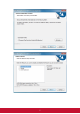
3. Software setup Run Setup to install the Video Wall Color Calibration software for use with Spyder 5 pod. It will automatically place the shortcut icon on the desktop when complete.
4
5
6
After install finished, the shortcut icon should place on the desktop.
4. Color Sensor Activation First, make sure that your Spyder5 is plugged into a USB port on your computer. Check the Device Manager and be sure that the driver is working (i.e, Datacolor Spyder5).
5. USB adapter cable check Plug in your USB-to-Serial Port conversion cable to the computer. Check the Device Manager and be sure that the driver is working (i.e., COM5). Otherwise install a working driver. Please note the COM Port the adapter cable was assigned by the system.
6. Performing Video Wall Color Calibration a. Run the video Wall Calibration software by double-clicking on the desktop icon. It will bring up the screen on the right.
b. Click on the Warm Up button to start the 10 countdown minute timer. Select COM port to match what was shown in the device manager for USB to serial conversion adapter cable. Select 9600 baud rate.
c. When the timer reaches 00:00, then click on the Color Sensor Setting button. Place the Spyder5 pod on the central area of the video wall and click Lighting Condition to get the ambient light reading. Click on the COM Port setting button to lock it in. Then click on the right arrow to move to the next step.
d. Drag the gray area to select your tiling configuration or select horizontal and vertical on the right upper area. Click the right arrow to move to the next step.
e. Current readings of each display will need to be taken before the actual calibration process. Mouse over to each display box to bring up the target screen. Mouse over to bring up gear In this case “mouse over” or “hover over” ID:1 display block. The gear will pop up. Place the color pod over the center “white” area in the gear. Click on the box. This will bring up the Measurement dialogue box.
f. Click on the Measure button to collect the color data g. The data taken will be displayed in the Measure Results window. Click on the “x” of the Measurement dialogue box to close it out.
h. The screen that was measured will show up as blue as shown here. Repeat e. thru g. for each screen until all screens show up as blue. i. All the screens show up with a blue background when all the data is taken. Click on the right arrow to move to the next step.
The measure data also show on the display. j. The software will automatically select the display with the lowest luminance as the target. You can choose any other screen for the target x,y coordinates to match up by clicking on the screen.
k. Here is an example where ID:1 was chosen as the target for the other screens to match. l. Click on the right arrow to move to the actual step to calibration all the other displays to the selected target screen.
m. Mouse over to display to be calibrated and place the color pod over the “white” area of the gear. Click on the box. The calibration process for that display will begin. Wait for it to complete.
n. Once complete, the background will turn blue. Mouse over each display to calibrate and repeat m. through n. n. Once all the other displays are calibrated, as shown here, click on the right arrow to move to the next step.
p. This is the verification stage. You can select each image to visually compare the images. You may mouse over any display and place the pod over the “white” area of the gear if you want to fine tune a specific display. Click on the box to bring up the fine tune screen. q. This is the fine tuning dialogue box. You can click measure to get the current reading of a specific display.
r. Click on the scales to change the RGB or contrast values to make changes. Please note that if you need more adjustment than the range allows, close out the fine tuning screen and go into it again, to make further adjustments to the values in the direction needed. You can click on the Measure button any time to check results of the changes. Close out the box when done. s. Fine tune each screen as desired. Click on the 3 test images to compare all the displays on your video wall.
Other Information Customer Support For technical support or product service, see the table below or contact your reseller. NOTE: You will need the product serial number. Country/Region Website T = Telephone C = CHAT ONLINE Email Australia New Zealand www.viewsonic.com.au AUS= 1800 880 818 NZ= 0800 008 822 service@au.viewsonic.com Canada www.viewsonic.com T (Toll-Free)= 1-866-463-4775 T (Toll)= 1-424-233-2533 service.ca@viewsonic.com Europe www.viewsoniceurope.com www.viewsoniceurope.