Video Wall Installation Guide User Guide IMPORTANT: Please read this User Guide to obtain important information on installing and using your product in a safe manner, as well as registering your product for future service. Warranty information contained in this User Guide will describe your limited coverage from ViewSonic Corporation, which is also found on our web site at http:// www.viewsonic.
Contents 1. Precaution 2. Note on moving the display 3. Installing the Product 3-1. Installation on an Indented Wall......................................................................6 3-2. Mounting in Portrait Position...........................................................................6 4. Tiling Display Function of Edge Alignment Kit ............................................................................8 Installing Edge Alignment Kit .....................................................
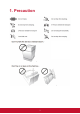
1.
2. Note on moving the display The display has limited mechanical strength. To prevent the display from performance failure caused by line defects, front bezel bending, glass scratch/ broken, light leakage, etc, it must be handled with care. Keep the original shipping box and packaging in storage for use in the future when you may meed to transport the product.
3. Installing the Product 3-1. Installation on an Indented Wall Plane view A Minimum 100mm B Minimum 100mm C Minimum 100mm When installing the product on an indented wall, allow at least the space specified above between the product and wall for ventilation 3-2. Mounting in Portrait Position This display can be installed in portrait position. 1. Remove the table stand, if attached. 2. Rotate 90 degrees clockwise.
4.
Function of Edge Alignment Kit ■ Keep adjacent Displace at the same plane and uniform gap. Installing Edge Alignment Kit ■ Before install edge alignment kit, displays must be mounted to video wall frame correctly. ■ Using“Thumb Screw” for easy installing. ■ Using“Edge Alignment Kit-1” on adjacent four displays.
■ Using “Edge Alignment Kit-2” on adjacent two displays.
5. Daisy Chain Monitors Cable connections 1. 2. 3. 4. Turn off all devices. Connect the first display with the video source (e.g. computer). Connect one end of the cable to the appropriate OUT port on the first display. Connect the other end of the cable to the appropriate IN port on the second display. Follow Step 2 ~ 3 to connect all displays. Refer to the user manual of the purchased model for the location of all input and output ports.
Signal Input Requirement Item 1 Category VGA Input 2 HDMI Input 3 DVI Input 4 I²C DDC signal 5 Audio Input 6 CVBS Input 7 Component video input Description • VGA sync input - TTL level, separate H/V sync only, “+” or “-” polarity, terminated with 2.2k impedance. • Video pixel rate: 13.5 MHz to 165 MHz • VGA analog RGB level - 0 ~ 700mV linear, positive polarity, terminated with 75 impedance. • Compliance with HDMI Specification 1.
8 9 10 No Signal Input While no signal at external inputs, screen will display no signal . USB Input Only Supply USB Flash@5V +-5%/500mA. Supported media format please refer short spec. RJ45/LAN Support LAN control & DLNA.
6. C ontrol Connection IR daisy-chain connection 1. Connect all displays using the IR cables. 2. Connect the supplied IR extender to the IR-IN at the back of the first display. 3. Aim the supplied remote control at the IR extender just connected within the motion range. 4. Now you are ready to control all displays using the remote control. Refer to the user manual of the purchased model for the operation of remote control.
RS232 daisy-chain connection 1. 2. 3. 4. 5. Make sure the ID number has been set for each display. Connect the computer to a display using a RS-232C serial null modem cable. Connect all displays using the RS-232C serial null modem cables. Go to Setting > Control Setting each display. Select RS-232C. Refer to the RS-232 protocol document. LAN connection 1. Connect the computer to a LAN switch or hub using a RJ45 cable. 2.
Control Indication Item 1 2 Category RS-232 Protocol LAN Protocol 3 External communication (RS232) Description Command through RS-232 or LAN should be compliance with the requirement enclosed. Please refer RS232 spec.
7. Setting the Tile Mode Tiling Mode In Tile Mode you can view an image in a larger scale by connecting multiple monitors. After all the displays are installed properly to a video wall, you need set the position of each display to determine how to display the input image. Without setting the display position, each display outputs the complete picture independently. Once the position is set, the video source (e.g.
If you prefer to show different pictures on the displays of the video wall, you will need to have independent video source for each display. Note: Though the video sources vary, you can still manage all displays via remote control, RS-232 commands, or LAN control in this case. Set tiling mode in OSD Enable Choose to {On} or {Off} the Tiling function. If {On}, the display will apply the settings in {H monitors}, {V monitors}, {Position}, and {Frame comp.}.
H monitors/V monitors Adjust displays on the horizontal/vertical side.
Position (Monitor ID will be set in sync with position) Adjust the position of this display in the screen matrix. Different video wall layouts and display position setup in landscape mode: The position is starting from the top left of the video wall, the number increases as it goes down or goes to the right. Different video wall layouts and display position setup in portrait mode: The position is starting from the bottom left of the video wall, the number increases as it goes up or goes to the right.
Frame Comp. Choose to turn the frame compensation function on or off. If turned on, the display will adjust the image to compensate for the width of the display bezels in order to accurately display the image.
8. Other OSD Setting Frame Comp. Choose to turn the frame compensation function on or off. If turned on, the display will adjust the image to compensate for the width of the display bezels in order to accurately display the image. Eco Mode Set the Eco mode to Normal if you need to power ON/OFF via LAN control. APM Set the APM to OFF if you don’t need automatic turn-off display when no signal after a while. Switch On State Choose the display status used for the next time you connect the power cord.
9. C olor Calibration for Video Wall A software program that enhances the image uniformity of all displays in a video wall application. You can also adjust color settings of each display easily on a host computer. Refer to the color calibration user manual (VideoWallCalibration_UG_ENG) for more detail.