Service Manual ViewSonic VP2130b-1 Model No. VS10773 21” Color TFT LCD Display (VP2130b-1_SM Rev. 1a Dec.
Copyright Copyright © 2005 by ViewSonic Corporation. All rights reserved. No part of this publication may be reproduced, transmitted, transcribed, stored in a retrieval system, or translated into any language or computer language, in any form or by any means, electronic, mechanical, magnetic, optical, chemical, manual or otherwise, without the prior written permission of ViewSonic Corporation.
TABLE OF CONTENTS 1. Precautions and Safety Notices 1 2. Specification 4 3. Front Panel Function Control Description 11 4. Circuit Description 21 5. Adjusting Procedure 34 6. Trouble Shooting Flow Chart 54 7. Recommended Spare Parts List 61 8. Exploded View And Exploded Parts List 65 9. Block Diagram 69 10. Schematic Diagrams 70 11.
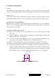
1. Precaution & Safety Notice 1. Caution : No modification of any circuit should be attempted . Service work should only be performed after you are thoroughly familiar with all of the following safety checks and servicing guide line 2. Safety Check : Care should be taken while servicing this LCD display. Because of the high voltage used in the inverter circuit. These voltage are exposed in such areas as the associated transformer circuits . 3.
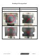
Handling & Placing method Correct methods : Incorrect Methods : Only touch the metal-frame of the panel or the front cover of Surface of the panel is pressed by fingers & this may cause the monitor . Do not touch the surface of the polarizer .
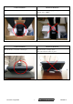
Correct methods : Incorrect Methods : Take out the monitor with cushion Take out the monitor by grasping the LCD panel. This may cause “ MURA“. Correct methods : Incorrect Methods : Place the monitor on a clean & soft foam pad . Place the monitor on foreign objects .
2.
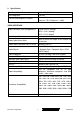
USB INTERFACE Up Stream Connector B type USB port x1 Down Stream Connector A type USB port x4 Compatibility Power Compliant with Revision 2.0 The hub gets power from the display. POWER SUPPLY Internal Power Supply Input Voltage Range Input Frequency Range Short Circuit Protection Over Current Protection Leakage Current Efficiency Fuse Power Dissipation Max Input AC Current Recovery Time Delta EADP-64BF 90 to 264 VAC 47.5 to 63 Hertz Output can be shorted without damage 5.0 A typical at 12.0 VDC 3.
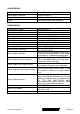
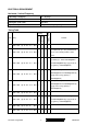
ELECTRICAL REQUIREMENT Horizontal / Vertical Frequency Horizontal Frequency 24 – 92 KHZ Vertical Refresh Rate 50 – 85* HZ. Maximum Pixel Clock 165 MHz Sync Polarity Independent of sync polarity. Timing Table 640 x 350 @ 70 Hz, 31.5 KHz ü ü SOG 1 Composite Separated Item Timing ü Digital - TMDS Analog Remark ü For Separated sync, Only horizontal full 2 640 x 350 @ 85 Hz, 37.9 KHz ü ü ü screen, The vertical position is at the center.
640 x 480 @ 75 Hz, 37.5 KHz ü ü ü ü 11 640 x 480 @ 85 Hz, 43.3 KHz ü ü ü ü 12 720 x 400 @ 70 Hz, 31.5 KHz ü ü ü ü For Separated Sync, Switch 13 720 x 400 @ 85 Hz, 37.9 KHz ü ü ü ü 640x400@85Hz and 720x400@85Hz by [1]+[2] short cut key (primery = 640x400@85Hz) 14 720 x 480 @ 60 Hz, 31.5 KHz ü ü 15 720 x 576 @ 50 Hz, 31.3 KHz ü ü 16 800 x 600 @ 50 Hz, 24.7 KHz ü ü ü ü 17 800 x 600 @ 56 Hz, 35.1 KHz ü ü ü ü 18 800 x 600 @ 60 Hz, 37.
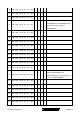
30 1152 x 864 @ 75 Hz, 67.5 KHz ü ü ü ü 31 1152 x 870 @ 75 Hz, 68.7 KHz ü ü ü ü 32 1280 x 720 @ 50 Hz, 37.5 KHz ü ü 33 1280 x 720 @ 60 Hz, 45 KHz ü ü For Separated and Composite sync, 34 1280 x 768 @ 50 Hz, 39.6 KHz ü ü ü ü Switch 1024x768@50Hz and 1280x768@50Hz by [1]+[2] short cut key (primery = 1024x768@50Hz) For analog sync, Switch 1280x768@60Hz 35 1280 x 768 @ 60 Hz, 47.
For analog sync, Switch 49 1400 x 1050 @ 60 Hz, 64.7 KHz ü ü ü 1400x1050@60Hz and 1680x1050@60Hz by [1]+[2] short cut key (primary = 1400x1050@60Hz) For Separated and Composite sync, 50 1400 x 1050 @ 60 Hz, 65.3 KHz ü Switch 1400x1050@60Hz and ü 1680x1050@60Hz by [1]+[2] short cut key (primary = 1400x1050@60Hz) 51 1400 x 1050 @ 75 Hz, 82.3 KHz ü ü ü ü 52 1440 x 900 @ 60 Hz, 55.5 KHz ü ü ü ü 53 1440 x 900 @ 60 Hz, 59.
User Presets Number of User Presets (recognized timings) Available: 10 presets total in FIFO configuration Changing Modes ● Maximum Mode Change Blank Time for image stability : 3 seconds (Max), excluding “Auto Adjust” time ● Under DOS mode (640 x 350, 720 x 400 & 640 x 400), it should recall factory setting when execute “Auto Adjust” ● The monitor needs to do “Auto Adjust” the first time a new mode is detected (see section “0-Touch™ Function Actions”) ● While running Change Mode, Auto Adjust or Memory Recal
3.
ViewSonic VP2130 Main Menu Controls Adjust the menu items shown below by using the up and down buttons. A. Auto Image Adjust automatically sizes, centers, and fine tunes the video signal to eliminate waviness and distortion. Press the [2] button to obtain a sharper image. NOTE: Auto Image Adjust works with most common video cards. If this function does not work on your LCD display, then lower the video refresh rate to 60 Hz and set the resolution to its pre -set value. B.
Fine Tune sharpens focus by aligning the illuminated text and/or graphic characters. Sharpness adjusts the clarity and focus of the screen image. This feature is disabled when the input signal is 1600x1200@60Hz analog signal. Scaling features are explained below: Fill All - the signal will be displayed on the whole screen and wide signal will be adjusted to 4:3 ratio.
OSD Function Menu A. When in Analog Input Mode 1. Main Menu Press the [1] (Menu) button to enter the Main Menu: Press the [▲] button to highlight the previous item or the [▼] button to highlight the next item. Press the [1] (Menu) button to exit the Main Menu. (1) Auto Image Adjust Page: Press the [2] button to execute the auto image adjust function. Press the [1] button to exit the page. (2) Contrast/Brightness Page: Press the [2] button to enter the contrast adjustment page.
Press the [1] button to exit the page. Red, Green, Blue Options: Press the [2] button to cycle among the colors. Press the [1] button to exit the page. Press the [▲] button to increase the selected color level. Press the [▼] button to decrease the selected color level. (6) Information Page: Press the [2] button to enter the information page. Press the [1] button to exit the information page. (7) Manual Image Adjust Page: Press the [2] button to enter the manual image adjustment page.
Press the [2] button to enter the setup menu page. Press the [1] button to exit the page. Press the [▲] button to highlight the previous item or the [▼] button to highlight the next item. 1) Language Select Item Press the [2] button to enter the language selection page. Press the [1] button to exit the page. Press the [▲] button to highlight the previous item or the [▼] button to highlight the next item. English, French… Option Press the [2] button to select the language.
Press the [1] button to exit the page. (9) Memory Recall Page Press the [2] button to execute the memory recall function. Press the [1] button to exit the page. 2. Other Menu: This “shortcut” menu is directly accessible without bringing up the OSD. (1) Contrast Dialog Press the [▲] or [▼] button to enter the Contrast Dialog. Press the [1] button to exit the Contrast Dialog. Press the [2] button to enter the Brightness Dialog. Press the [▲] button to increase the contrast.
(3) Input Select Page: Press the [2] button to switch to analog input mode. (4) Audio Adjust Page: Press the [▲] button to increase the volume. Press the [▼] button to decrease the volume. Press the [2] button to enable or disable mute function . Press the [1] button to exit the page. (4) Color Adjust Page: Press the [2] button to enter the color adjustment page. Press the [1] button to exit the page. Press the [▲] button to highlight the previous item or the [▼] button to highlight the next item.
Press the [▲] button to highlight the previous item or the [▼] button to highlight the next item. 1) Language Select Item Press the [2] button to enter the language selection page. Press the [1] button to exit the page. Press the [▲] button to highlight the previous item or the [▼] button to highlight the next item. English, French… Option Press the [2] button to select the language. Press the [1] button to exit the page. 2) Resolution Notice Item Press the [2] button to enter the resolution notice page.
(8) Memory Recall Page Press the [2] button to execute the memory recall function. Press the [1] button to exit the page. 2. Other Menu: This “shortcut” menu is directly accessible without bringing up the OSD. (1) Contrast Dialog Press the [▲] or [▼] button to enter the Contrast Dialog. Press the [1] button to exit the Contrast Dialog. Press the [2] button to enter the Brightness Dialog. Press the [▲] button to increase the contrast. Press the [▼] button to decrease the contrast.
4. Circuit Description 1. Outline Buttons on the front panel: Power On/Off button, button 2 (ENTER / INPUT SELECT), up arrow button, down arrow button, button 1 (MENU). D-sub 15pin connector, DVI-I connector and AC-IN jack are located on the back side of the cabinet.
Video signal connector for digital input: 29pin DVI-D,DVI-A connector CN2 Pin No. 25 RX2RX2+ GND RX4RX4+ SCL SDA VS RX1RX1+ GND RX3RX3+ 5V GND HP RX0RX0+ GND RX5RX5+ GND RXC+ RXCRED GRN BLU HS GND 1 2 3 4 5 6 7 8 9 10 11 12 13 14 15 16 17 18 19 20 21 22 23 24 C1 C2 C3 C4 C5 Signal Name Description 1 RX2- TMDS negative differential input, channel 2 2 RX2+ TMDS positive differential input, channel 2 3 GND Logic Ground 4 RX4- Reserved. No connection 5 RX4+ Reserved.
3. ELECTRICAL SPECIFICATIONS Standard conditions Display Area 408.0 x 306.0 mm Video Signal 0.7Vpp Contrast Default Brightness Max. Ambient 20 +/- 5 ° C Input AC 110~ 240V Warming up > 30 min Display 1600X1200 POWER Power supply Input voltage 100~240Vac Power frequency 50~60Hz Input current <1.
Sync input: > 1 k ohm 4. SIGNAL CABLE: Signal cable with Mini D-Sub 15P connectors at both ends. Length: 1.8 meter.
5.
Display Type = R/G/B Color (25-34) CHROMA INFO: Red X - 0.648 Green X - 0.289 Blue X - 0.143 White X - 0.313 Red Y - 0.339 Green Y - 0.598 Blue Y - 0.078 White Y - 0.
Sync Offset: 64 pixels Sync Pulse Width: 192 pixels Border: 0 pixels Frequency: 75.00 KHz Vertical: Active Time: 1200 lines Blanking Time: 50 lines Sync Offset: 1 lines Sync Pulse Width: 3 lines Border: 0 lines Frequency: 60.
Digital EDID 128 BYTES OF EDID CODE: 0 1 2 3 4 5 6 7 8 9 ________________________________________ 0 | 00 FF FF FF FF FF FF 00 5A 63 10 | 1C 13 01 01 01 01 01 0F 01 03 20 | 80 29 1F 78 2E 30 85 A6 56 4A 30 | 99 24 14 50 54 BF EF 80 A9 40 40 | 90 4F 90 40 81 80 81 40 71 4F 50 | 31 0A 01 01 48 3F 40 30 62 B0 60 | 32 40 40 C0 13 00 98 32 11 00 70 | 00 1E 00 00 00 FF 00 50 53 42 80 | 30 35 30 31 30 30 30 30 31 0A 90 | 00 00 00 FD 00 32 4B 1E 5C 11 100 | 00 0A 20 20 20 20 20 20 00 00 110 | 00 FC 00
Red Y - 0.339 Green Y - 0.598 Blue Y - 0.078 White Y - 0.
Vertical: Active Time: 1200 lines Blanking Time: 50 lines Sync Offset: 1 lines Sync Pulse Width: 3 lines Border: 0 lines Frequency: 60.
6. THEORY OF OPERATION This section describes the function of the LCD monitor per functional block. This monitor includes MB board, power board and button board and USB board 6.1 MB BOARD The MB board is a Four-layer, single -landed design with ground and internal planes provided. DC power from the power board enters the board through a 8P connector. The other connector on the board is for the button board.
c) SST 39VF040 Micro Controller: The SST 39VF040 micro controller (MCU) serves as the system micro controller.
Input Output Rated Input Voltage 20Vdc Input Voltage Range 19 ~ 21 Vdc Input Current 1.8A(MAX) On / Off control Voltage 2.5~5.25 for on , 0~1 for off Rated Output Strike-on Voltage 1800Vrms Rated Output Voltage 700~900Vrms Rate Output Frequency 35~80KHz Rated Output Current 5.5~8.0 mA 6.3.2 power This is a general purpose AC / DC adapter which converts 90~240 Vac to a stabilized DC voltage: 12 Volts, with a rated output current of 2.4A. The electrical specification is described below.
5. Adjusting Procedure 1. Function test (1) Test equipment Color video signal and pattern generator (or PC with WUXGA resolution) (2) Test condition Before function testing and alignment, the unit must warm up for at least 30 minutes under the following conditions: 2. 1. Room temperature 2. With full-white screen , RGB , black pattern 3. with cycled display modes. Test display modes Timing Table Timing Analog 31.5 KHz 2 640 x 350 @ 85 Hz, 37.
10 640 x 480 @ 75 Hz, 37.5 KHz ü ü ü ü 11 640 x 480 @ 85 Hz, 43.3 KHz ü ü ü ü 12 720 x 400 @ 70 Hz, 31.5 KHz ü ü ü ü 13 720 x 400 @ 85 Hz, 37.9 KHz For Separated Sync, Switch ü ü ü ü 640x400@85Hz and 720x400@85Hz by [1]+[2] short cut key (primery = 640x400@85Hz) ü 14 720 x 480 @ 60 Hz, 31.5 KHz 15 720 x 576 @ 50 Hz, 31.3 KHz 16 800 x 600 @ 50 Hz, 24.7 KHz ü 17 800 x 600 @ 56 Hz, 35.
38 1280 x 768 @ 85 Hz, 68.6 KHz ü ü ü ü 39 1280 x 960 @ 50 Hz, 49.4 KHz ü ü ü ü 40 1280 x 960 @ 60 Hz, 59.7 KHz ü ü ü ü 41 1280 x 960 @ 75 Hz, 75.2 KHz ü ü ü ü 42 1280 x 960 @ 85 Hz, 85.9 KHz ü ü ü ü 43 1280 x 1024 @ 50 Hz, 52.7 KHz ü ü ü ü 44 1280 x 1024 @ 60 Hz, 64 KHz ü ü ü ü 45 1280 x 1024 @ 75 Hz, 80 KHz ü ü ü ü 46 1280 x 1024 @ 85 Hz, 91.1 KHz ü ü ü ü 47 1360 x 768 @ 60 Hz, 47.
blanking. *3. The image quality of 85Hz mode might be worse than 75Hz.
Viewsonic Corporation Pattern 1 Pattern2 Pattern 3 Pattern4 Pattern 5 Pattern6 38 Confidential - Do Not Copy VP2130b-1
Pattern 7 Pattern 8 Pattern 9 Viewsonic Corporation 39 Confidential - Do Not Copy VP2130b-1
Firmware update procedure : When you received a received monitor , please check whether the firmware version. upgrade to the latest version . If not , please following procedure to 1.
2. Connection : The 9-pin serial cable connects the com port of PC and the Genesis firmware update board. VP2130 and the Genesis firmware update board is connected by VGA cable. The male A to male B USB cable connects the PC and Genesis firmware update board. Appendix A : How to install the software for ISP : 0. To setup ISP environment : Hardware: PC or notebook, 9-pin serial cable, VGA cable and USB cable (Male A to Male B). If your PC does not have serial port, please get a USB to RS232 cable.
0.1 Double-click the “ GProbe5.0.exe” in Windows & install the program. , see Fig 0.1 Fig 0.1 0.2 Keep on press “ Next “ 4 times to go through the installation processes, see Fig. 0.2 Fig. 0.
0.3 Check the “I accept the agreement” then press “ Next “ , see Fig. 0.3 Fig. 0.3 0.4 Keep on press “ Next “ , see Fig. 0.4 Fig. 0.
0.5 Keep on press “ Next “ , see Fig. 0.5 Fig. 0.5 0.6 Click “Next” to start the installation. See Fig 0.6 Fig. 0.
0.7 If you see this message, click “Yes”. See Fig 0.7. Fig. 0.7 0.8 If you see the Fig 0.8, click “Finich” button to restart the system. Fig. 0.8 0.
Appendix B : How to use software to upgrade the BIOS : 1.1 After installation , we could find the shortcut in the setting path or the program bar ( default setting ) , see Fig 1.1 Fig. 1.1 1.2 Move your mouse cursor to GProbe 5 and click it. You will see the Fig. 1.2 Fig. 1.2 1.3 Please create a directory such as “ISP” below the root directory (the path is “drive letter”:\ISP now).
1.4 Copy the create a text file with the following string and save it as “ISP.txt” SetBuffer 0x1000 4096 RAMWrite d:\GNSSISP\loader.hex Run 0x500 RAMWrite d:\GNSSISP\isp8.hex Run 0x580 FlashErase FastFlashWrite d:\GNSSISP\rd_monitor.hex 1.5 Set the monitor to Factory Mode by pressing “2” and “Power” at the same time. 1.6 Click the right-lower terminal window and type “batch d(or other drive letter):\ISP\isp.txt” in the upper blank area then click “Execute” button. See the Fig 1.3. Fig. 1.
1.7 After click the “Execute” button, you will see the terminal information in Fig. 1.4 . When the message “Batch: command successful” is shown, the flash progress is completed. Fig. 1.
VP2130b-1 / VP2130b-1H series de-assembling procedure 1. Move the monitor our from carton 2. Put the monitor on desk & face down 3. Remove the VESA cover 4. Loose the screws & remove the stand 5. Separate the hook by tool (coin or screw-driver) 6.
7. Loose the INVERTER SHIELDING SCREW 8. Tear off the yellow tape &Pull out the CCFL cables 9. Loose the INVERTER/B screw 10. Loose the SHIELDING SCREW 11. Tear off the yellow tape &Pull out the LVDS CABLE 12.
15. Loose the bezel 16.Remove the Button/B 17. Loose the shield 18. Remove the PCBA & mylar 19. Loose the IO-NUT SCREW 20.
19. Loose the BKT-T/B SCREW Viewsonic Corporation 20.
VP2130b-1 / VP2130b-1H Series packing method 1. Sticker on LCD protection film 3. Put on the end-cap left / right 2. Put the monitor into the PE or EPE bags 4. Put the monitor into carton Face-up 5. Put all accessories into carton 6.
6. Trouble Shooting Flow Chart Monitor Cann't BootUp Change Power Board Change Key Button Change Crystal Change M/B NG NG NG NG Check Power Board CN7 PIN 1,2 Check Key Bottom Check Crystal X1 Check M/B 5V,3.3V.2.5V 1.
Black Screen Change Power Board Change Scalar M/B Change Scalar M/B NG NG NG Check Panel Vcc 5V Check M/B Panel ON/OFF CN7 PIN 8 3.3V Check M/B CN7 PIN 7 Brightness MAX 3.
No Signal Change VGA Card Change VGA Cable Change Scalar M/B NG Check VGA CARD NG Check VGA Cable NG Check H/V Sync U22 PIN 14,15 Check CN5 Pin Signal Change Scalar M/B Change Scalar M/B Viewsonic Corporation 56 Confidential - Do Not Copy VP2130b-1
No Signal In DVI-D Change VGA Card Change DVI Cable Change Scalar M/B NG Check VGA CARD NG Check DVI-D Cable NG Check H/V Sync U22 PIN 14,15 Check CN5 Pin Signal Change Scalar M/B Change Scalar M/B Viewsonic Corporation 57 Confidential - Do Not Copy VP2130b-1
No Signal In DVI_A Contact To VGA Card Seller Change DVI Cable Change Scalar M/B NG NG NG NG Change Scalar M/B Check VGA Card Support DVI-A Signal Check DVI Cable Check H/V Sync U22 PIN 14,15 Check CN5 Signal Change Scalar M/B Viewsonic Corporation 58 Confidential - Do Not Copy VP2130b-1
U.S.B doesn't Work Device Problem Change Scalar M/B Change USB M/B Change USB M/B NG NG NG NG Check USB M/B R20 5V Check USB M/B CN6 PIN1,2 Check USB M/B U3 3.
OSD Pivot doesn't Work Solder R178 Both Ends Change Scalar M/B NG Check R178 Voltage 3.
7. Recommended Spare Parts List RECOMMENDED SPARE PARTS LIST (VP2130b-1) ViewSonic Model Number: VS10773-1W Rev: 1b Serial No.
RECOMMENDED SPARE PARTS LIST (VP2130b-1) ViewSonic Model Number: VS10773-1W Rev: 1b Serial No.
BOM LIST (VP2130b-1) ViewSonic Model Number: VS10773-1W Rev: 1a Serial No. Prefix: PSD Item 1 2 3 ViewSonic P/N #N/A B-00004349 #N/A Ref.
Item ViewSonic P/N 57 M-SCW-0824-0795 58 #N/A Ref. P/N MM40080BCI5 27LAVPCS007 Description SCREW M4.0*8-B(NI,NYLOK)GP LAVP CHASSIS ASSY GP STAND VISA COVER EALAVP03011 LAVP(EALAVP03,REV3A)GP MM30060BBJ3 SCREW M3.0*6,B(NI) GP LAVP PANEL DEPENDENT KIT ASSY(SASN) 2ALAVPPTS07 GP AAM213U6008 LCD 21" LTM213U6-L01(1600*1200,UXGA)GP LAVP SW BIOS IMAGE(SASN)GM1601-LF-CF AZLAVP0S009 N/A INV AS023190407 MODULE(SEL)LAVP(20V,V=900V,MAX)GP 28LAVPPK004 LAVP PACKING ASSY GP DDWCVPDV019 CABLE DVI-I(29/29P,1.
8.
Cable connection diagram 33 CN2 CN1 CN1 PANEL LVDS 34 CN4 CN5 CN2 CN3 Main board To panel Inv.
EXPLODED PARTS LIST (VP2130b-1) ViewSonic Model Number: VS10773-1W Rev: 1a Serial No.
PACKING PART LIST ( VP2130b-1 ) ViewSonic Model Number: VS10773-1W Rev: 1b Serial No. Prefix: PSD Item 1 2 3 4 5 6 7 8 9 10 11 12 13 14 15 Viewsonic Corporation 68 Confidential - Do Not Copy VP2130b-1 ViewSonic P/N CB-00004361 A-PC-0106-0224 CB-00004360 P-00004159 P-00004429 #N/A M-LB-0813-0747 #N/A M-LB-0813-0745 M-LB-0813-1042 P-00004428 DC-00004425 #N/A M-00004427 #N/A Ref. P/N Description Q'ty DDWCVPDV019 DVI cable 1 DM333181G97 POWER CORD 3P 1.
74HCT4053 69 DVI VS +5V 74HCT4053 HS DSCL +5V TX RX SDA SCL VS HS HS 74HCT4053 DSDA +5V SCL RGB Analog SDA ASCL Viewsonic Corporation ASDA B G R 24LC02 +5V 24LC02 +5V RXC- RXC+ DVI_B DVI_G DVI_R RX0+ ~RX2+ RX0- ~RX2- 74HCT4053 +5V SDA SCL Interface DVI Interface Triple ADC KEYPAD GM1601 OCMADDR,OCMDATA FSCLK- FSCLK+ FSDATA,FSADDR CLK- CLK+ LVDS+,LVDSPANEL BACKLIGHT +12V AIC1577 ADJ POWER BLOCK SST39VF040 +3.3V K4D263238G-VC33 +3.3V RESET +3.
10.
100K 3 DVI_RED+ Confidential - Do Not Copy 1 D21 DAN217K/NC 2 3 RX0+ VP2130b-1 D22 DAN217K/NC 3 RX0- 2 1 D20 DAN217K/NC +5V 3 RX1- 2 3 RX1+ 2 3 RX2- +5V 1 +5V 1 1 3 RX2+ +5V D18 D19 DAN217K/NC DAN217K/NC 2 2 2 2 D16 D17 DAN217K/NC DAN217K/NC 3 RXC- 3 RXC+ 71 1 1 D15 DAN217K/NC +5V C8 0.01u C5 47uF/6.3V R12 R186 10K(NC) BK2125HS102/8 10K 75R/NC R19 75R/NC R18 BK2125HS102/8/NC C7 0.
VSS OCMADDR19 T3 OCMADDR18 T2 OCMADDR17 T1 OCMADDR16 U4 OCMADDR15 U3 OCMADDR14 U2 OCMADDR13 U1 OCMADDR12 V4 OCMADDR11 V3 OCMADDR10 V2 OCMADDR9 V1 OCMADDR8 W3 OCMADDR7 W2 OCMADDR6 W1 OCMADDR5 Y3 OCMADDR4 Y2 OCMADDR3 Y1 OCMADDR2 AA3 OCMADDR1 AA2 OCMADDR0 AA1 OCMADDR11 OCMADDR13 OCMADDR14 OCMADDR15 INT_OSC 8-BIT_FLASH2 8-BIT_FLASH1 8-BIT_FLASH3 R147 R148 10K 10K OCMADDR16 OCMADDR18 OCMADDR17 OCMADDR19 BGA416-26X26_1_27 GM1601 DVI_GND DVI_GND DVI_GND DVI_GND DVI_GND DVI_GND DVI_GND 10K 10K 10K 10K A7
FSCLKFSCLK+ FSCKE 5 5 5 5 FSDQS0 FSDQS1 FSDQS2 FSDQS3 5 5 5 5 FSDQM0 FSDQM1 FSDQM2 FSDQM3 /FSRAS /FSCAS /FSWE FSDQS0 FSDQS1 FSDQS2 FSDQS3 M12 M11 N12 N2 M2 L2 L3 B2 H13 H2 B13 CLK CLK CKE CS RAS CAS WE DQS0 DQS1 DQS2 DQS3 FSDQM0 FSDQM1 FSDQM2 FSDQM3 B3 H12 H3 B12 DM0 DM1 DM2 DM3 C4 C11 H4 H11 L9 L12 L13 M3 M4 M10 N3 NC NC NC NC NC NC NC NC NC NC NC FSCLK+ R149 140R FSCLK- R207 Place R602 termination close to corresponding U600 Pins +2.5V_DDR 0R(NC) +2.
R222 47 10K/6 R162 330U/16V USB_CTRL C 0.1u/NC +5V R167 1 S USB_VDD 4 CN6 4 2 3 2 1 0.1u 0.1U/6 3 1 R168 R216 0/NC ENTERY_3273-G04N B 330u/16V 1 DTC144EUA 2 C175 C173 2.2K 3 3 G2 Q3 C174 L20 CX000800000 8 7 6 5 0.1u R158 C166 2 4.7K 1u 4.7K Panel_Power 2 2200P/6 5 PPWR C169 1 2 3 4 Q4 AO4411 MMBT3904 C170 R84 C168 1 2200P/6 + C215 220u/35V/NC 2 220u/35V/NC MC7818/CASE936/NC 4.7K/NC 10K/6 C214 C207 GND C204 330u/16V C211 0.
11. PCB Layout Diagrams 11.
11.
11.
11.
11.
11.
11.
* Reader’s Response* Dear Readers: Thank you in advance for your feedback on our Service Manual, which allows continuous improvement of our products. We would appreciate your completion of the Assessment Matrix below, for return to ViewSonic Corporation. Assessment A. What do you think about the content of this Service Manual? Unit Excellent Good Fair Bad Excellent Good Fair Bad 1. Precautions and Safety Notices 2. Specification 3. Front Panel Function Control Description 4. Circuit Description 5.