Service Manual ViewSonic VX2235wm-1 Model No. VS11349 22” Color TFT LCD Display (VX2235wm-1_SM Rev. 1a Aug.
Copyright Copyright © 2006 by ViewSonic Corporation. All rights reserved. No part of this publication may be reproduced, transmitted, transcribed, stored in a retrieval system, or translated into any language or computer language, in any form or by any means, electronic, mechanical, magnetic, optical, chemical, manual or otherwise, without the prior written permission of ViewSonic Corporation.
TABLE OF CONTENTS 1. Precautions and Safety Notices 1 2. Specification 3 3. Front Panel Function Control Description 13 4. Circuit Description 19 5. Adjustment Procedure 20 6. Troubleshooting Flow Chart 54 7. Recommended Spare Parts List 62 8. Exploded Diagram and Exploded Parts List 64 9. Block Diagram 67 10. Schematic Diagrams 68 11.
1. Precautions and Safety Notices 1. Appropriate Operation (1) Turn off the product before cleaning. (2) Use only a dry soft cloth when cleaning the LCD panel surface. (3) Use a soft cloth soaked with mild detergent to clean the display housing. (4) Use only a high quality, safety approved AC/DC power cord. (5) Disconnect the power plug from the AC outlet if the product will not be used for a long period of time.
Correct methods : Only touch the metal-frame of the panel or the front cover of the monitor. Do not touch the surface of the polarizer . Incorrect Methods : Surface of the panel is pressed by fingers & this may cause “ MURA “ Take out the monitor with cushion Take out the monitor by grasping the LCD panel. That may cause “ MURA“. Place the monitor on a clean & soft foam pad . Place the monitor on foreign objects .
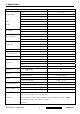
2. Specification 2.1 INSTRUCTION FEATURES VX2235wm Size 22 " wide TFTLCD PANEL Luminance (Typ) 280 cd/㎡ 1st Contrast Ratio (Typ) 700:1 Colors 16.2 M (6 bits + 2 bits FRC) CMO Response Time 5 ms(on/off) A220Z1 Viewing Angle (H/V) 170 ° / 160 ° Recommend resolution Input Signal Sync Compatibility Compatibility Power Voltage Power Consumption Audio Ergonomics OSD Control Dimension Weight Operating Condition Storage Condition 1680x1050@60Hz Analog Yes (75ohms, 0.7/1.
2.2 GENERAL SPECTION Test Resolution & Frequency 1680x1050 @ 60Hz Test Image Size Full Size Contrast and Brightness Controls Factory Default: Contrast = 70%, Brightness = 100% 2.
2.
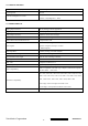
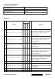
2.5 ELECTRICAL REQUIREMENT Horizontal / Vertical Frequency Horizontal Frequency 24 – 82 kHz Vertical Refresh Rate 50 – 85* Hz Maximum Pixel Clock 150 MHz Sync Polarity Independent of sync polarity. Timing Table SOG Composite Separated Item Timing Digital - TMDS Analog Remark For Analog sync, the image vertical size image 1 640 x 350 will be not full screen (Still at the center), And the @ 70 Hz, 31.5 KHz OSD will be 640x350/640x400/720x400 (primary= 720x400).
640 x 480 @ 75 Hz, 37.5 KHz 11 640 x 480 @ 85 Hz, 43.3 KHz For Analog sync, the image vertical size image 12 720 x 400 will be not full screen (Still at the center), And the @ 70 Hz, 31.5 KHz OSD will be 640x350/640x400/720x400 (primary= 720x400). For Analog sync, the image vertical size image 13 720 x 400 will be not full screen (Still at the center), And the @ 85 Hz, 37.9 KHz OSD will be 640x350/640x400/720x400 (primary = 720x400).
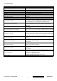
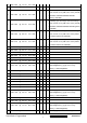
1280x768@85Hz by [1]+[2] short cut key (primary = 1024x768@85Hz) 35 1280 x 960 @ 50 Hz, 49.4 KHz 36 1280 x 960 @ 60 Hz, 59.7 KHz 37 1280 x 960 @ 75 Hz, 75.2 KHz 38 1280 x 1024 @ 50 Hz, 52.7 KHz 39 1280 x 1024 @ 60 Hz, 64 KHz 40 1280 x 1024 @ 70 Hz, 74.6 KHz 41 1280 x 1024 @ 72 Hz, 76.8 KHz 42 1280 x 1024 @ 75 Hz, 43 1360 x 768 80 KHz @ 60 Hz, 47.7 KHz 44 1400 x 1050 @ 50 Hz, 54.1 KHz 45 1400 x 1050 @ 60 Hz, 64.7 KHz For analog sync,, Switch 1400x1050@60Hz and 46 1400 x 1050 @ 60 Hz, 65.
2.6 FRONT PANEL CONTROLS AND INDICATORS Front Panel Hardware Controls Power Switch (Front Head) Power Control, soft Power Switch. Power LED (Front Head) Blue – ON Orange – Active Off Dark = Soft Power Switch OFF [ 1 ] BUTTON 1 [ 2 ] Button 2 Front Panel Controls (Head) [ 1 ] [ 2 ] [ ] [▼] [▲] [ ] Power [▼] DOWN ARROW BUTTON [▲] UP ARROW BUTTON Note: Power Button, Button 1 and Button 2 must be one-shot logic operation. (i.e. there should be no cycling) Reaction Time OSD must fully appear within 0.
Main Menu Controls Auto Image Adjust*1 Contrast/Brightness*2*4 Input Select Analog, Digital Audio Adjust Volume*4, Mute*4 Color Adjust SRGB, 9300K,7500K, 6500K(default), 5400,User Color [R, G, B] Information [H Frequency, V Frequency, Resolution, Pixel Clock, Serial Number, Model Number, [“www.ViewSonic.com” ] Manual Image Adjust Horizontal Size*1, H/V.
failure. If the power button is not in the locked mode, then power should return to it's previous state when power is restored after a power failure. The power button lock will be deactivated by pressing the front panel control buttons "(1), & (▼)" again for 10 seconds.
2.7 AUDIO INTERFACE (SPEAKER SPECIFICATION) Line input signal 1.0 Vrms @1kHz Line input impedance 10 kOhm Maximum Amp power output (Watt) 2 W (RL=4Ω) Amp -THD < 10 % THD @1kHz Speaker Power rating(Ω/Watt) 4Ω/2.5 W (TYP.) ; 4Ω/ 3 W (MAX) Signal to Noise Ratio 72 dB Frequency response Fo – 20kHz SPL. 85 ± 3 dB (at 0.5m) FO 300 Hz Line input connection 3.5 mm stereo jacks There should be no audible vibration resonance at volume=100% & Vibration Screen image treble / bass in def.
3. Front Panel Function Control Description Adjusting the Screen Image Use the buttons on the front control panel to display and adjust the OSD controls which display on the screen. The OSD controls are explained at the top of the next page and are defined in “Main Menu Controls” on page 10. Main Menu with OSD controls Front Control Panel shown below in detail Standby Power On/Off Power light Blue = ON Orange = Power Saving Displays the control screen for the highlighted control.
Do the following to adjust the display setting: 1. To display the Main Menu, press button [1]. NOTE: All OSD menus and adjustment screens disappear automatically after about 15 seconds. This is adjustable through the OSD timeout setting in the setup menu. 2. To select a control to adjust, pressSorTto scroll up or down in the Main Menu. 3. After the desired control is selected, press button [2]. A control screen like the one shown below appears.
Main Menu Controls Adjust the menu items shown below by using the up S and down T buttons. Control Explanation Auto Image Adjust sizes and centers the screen image automatically. Contrast adjusts the difference between the image background (black level) and the foreground (white level). Brightness adjusts background black level of the screen image. Input Select toggles between inputs if you have more than one computer connected to the VX2235wm.
Control Explanation 9300K-Adds blue to the screen image for cooler white (used in most office settings with fluorescent lighting). 7500K - Adds blue to the screen image for cooler white (used in most office settings with fluorescent lighting). 6500K-Adds red to the screen image for warmer white and richer red. 5400K-Adds green to the screen image for a darker color. User Color Individual adjustments for red (R), green (G), and blue (B). 1. To select color (R, G or B) press button [2]. 2.
Control Explanation Horizontal Size adjusts the width of the screen image. H./V. Position (Horizontal/Vertical Position) moves the screen image left or right and up or down. Fine Tune sharpens the focus by aligning text and/or graphics with pixel boundaries. NOTE: Try Auto Image Adjust first. Sharpness adjusts the clarity and focus of the screen image. OptiColor Mode provides an optimum display environment depending on the contents displayed. It contains 7 user-selectable presets.
Control Explanation Setup Menu displays the menu shown below: Language Select allows the user to choose the language used in the menus and control screens. Resolution Notice allows the user to enable or disable this notice. If you enable the Resolution Notice shown above and your computer is set at a resolution other than 1680 x 1050, the following screen appears. OSD Position allows the user to move the OSD menus and control screens. OSD Timeout sets the length of time the OSD screen is displayed.
4. Circuit Description 1.RTD 2553V Realtek RTD2553V series products are all-in-one LCD monitor controllers supporting UXGA / WSXGA+ / WXGA+ / SXGA (optional), and integrate Realtek high performance ADC, TMDS Rx(optional),scaling engine, OSD engine, LVDS Tx, RSDS Tx and so on. Moreover, all products are pin compatible in QFP128-pin package to save cost and make the design easier. 2. RTD2120 This chip is the micro-processor of LCD monitor.
5. Adjustment Procedure A. Function Test and Alignment Procedure 1. All Modes Reset You should do “All Model Reset” (Refer to Chap 3. Hot Keys for Function Controls) first. This action will allow you to erase all end-user’s settings and restore the factory defaults. 2. Auto Image Adjust The Auto Adjust is aimed to offer a best screen quality by built-in ASIC. For optimum screen quality, the user has to adjust each function manually. A.Turn the computer and LCD monitor on. B.
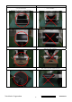
10. Black Box Test Signal: 1280*1024@60Hz Test Pattern: Window standard pattern Inspection Item: Bright Dot, Line Defect & Power 11. RED Test Signal: 1280*1024@60Hz Test Pattern: Full Screen Red Inspection Item: Bright Dot, Partial & Line Defect 12. Green Test Signal: 1280*1024@60Hz Test Pattern: Full Screen Green Inspection Item: Bright Dot, Partial & Line Defect 13. Blue Test Signal: 1280*1024@60Hz Test Pattern: Full Screen Green Inspection Item: Bright Dot, Partial & Line Defect 14.
Figure 1 Figure 2 Figure 3 Figure 4 Figure 5 Figure 6 Figure 7 Figure 8 ViewSonic Corporation Confidential - Do Not Copy 22 VX2235wm-1
B BIOS update procedure 1. To setup ISP environment Hardware: PC or Notebook , Parallel(Printer) cable , ISP tool( Fig 1) Software: ISP driver . If the O.S. was Win2000 or Win XP please have to install PORT95NT.
Fig 2 ViewSonic Corporation Confidential - Do Not Copy 24 VX2235wm-1
2. Install ISP 2.1 User could download ISP driver and PORT95NT install file from Myson Century website( //www.myson.com.tw ) 2.2 After extracting the zip file, the total files list as Fig 2.2, and double click the file of setup.exe to install. Fig 2.2 2.3 Press “Next" button to continue., see Fig 2.3 Fig 2.
2.4 Keep default setting or press “Change" button for selecting the path that you want , and then press“Next"button to continue, see Fig 2.4. Fig 2 4 2.5 Press “Install" button to continue, see Fig 2.5 Fig 2.
2.6 The Installer Information shows package warning, press “Ignore" button to continue, see Fig 2.6. Fig 2.6 2.7 Installation has finished, press “Finish" button, see Fig 2.7. Fig 2.
3. ISP security code 3.1 After installation, we could find the shortcut in the setting path or the program bar (default setting), see Fig 3.1. Fig 3.1 2.2 Security file is a key to use ISP function, press “確定" button, see Fig 3.2. Fig 3.
3.3 The warning is used to remind user of that different CPU rate may cause ISP function fail(it is limited by IIC protocol), press “確定" button, see Fig 3.3. Fig 3.3 2.4 Press“Create Security File" button to key in security code. Adjusting bar to decrease speed of IIC bus, see Fig 3.4. Fig 3.
3.5 At least 2 Command No of security code, see Fig 3.5, and different security code between hardware ISP and software ISP. The security code of software ISP is set by user while coding, but the security code of hardware ISP is set by Myson Century. Fig 3.
3.6 Fig 3.6 shows the setting for security code of hardware ISP, it needs 4 Command No, and key in command sequentially for 94, 94, AC, CA, 53. Fig 3.
3.7 Fig 3.7 shows the setting for security code of software ISP, it needs 2 Command No, and key in command sequentially for 7C, 4C, 77. The Command No and command must be set by user while coding. About the detail of setting, please refer to Section 6 Boot code of ISP. Fig 3.
4. Use ISP to program MCU 4.1 Select MTV type first, load the binary or Intel hex file that you want to program into the MCU, and select “Auto" item, then press “RUN" button, see Fig 4.1. 4.2 If user changes the MTV type, it must load file again, or the buffer of load file will be cleared. 4.3 CRC (cyclic redundancy check): the host can check CRC register's result instead of reading every byte in flash. The message of Check MCU CRC OK means that the Host verify ok for the progress of program. Fig 4.
5 Use ISP to read MCU content 5.1 Only software ISP could read the MCU content, it is according to program the boot code while coding. The limitation is used for the security of customer's code. Select “Read Target" item, and press“RUN" button, the MCU content will show as Fig 5.1. Fig 5.
5.2 If user uses hardware ISP to read MCU content, it shows as Fig 5.2. Fig 5.
6 Re-entry the ISP Mode When you could not select or click `Reset MCU' button and enter ISP mode again, you refer the message as below: ViewSonic Corporation Confidential - Do Not Copy 36 VX2235wm-1
Note: (1)Disable the `Enter ISP Mode' option to avoid the error message display. (2)If you using the MTV312M64 or before MCU serials, the MCU will always in `ISP Mode'even programming fail or erase MCU that instead of select or press `Reset MCU'.
7. Boot code of ISP 7.1 Hardware ISP (1) Without boot code (2) Fixed security code: 94, 94, AC, CA, 53 (3) Attention to the pin of HSCL (1) and HSDA (1) should keep in enable (4) MTV412M, MTV512M, CS8954 support hardware ISP 7.2 Software ISP (1) With boot code (2) User define the security code (3) Attention to the pin of HSCL (1) and HSDA (1) should keep in enable (4) Only software ISP could read the MCU content (5) MTV212M, MTV312M, MTV230M, MTV412M, MTV512M, CS8954 support software ISP 7.
7.4 The followings show the relationship between the code and the security code.
8. ISP Adaptor Schematic 9.
C. Packing For Shipping And Disassembly Procedure Packing For Shipping 1. Packing Procedure 1.1 Paste protection film to protect the monitor. (Figure 1) 1.2 Put the monitor in the PE bag and seal the bag with tape. (Figure 2) Figure 1 Figure 2 1.3 Put the cushion into the carton then place the monitor on the cushion. (Figure 3) 1.4 Put the cushion then place the seat assy and all the accessories into the carton. As last, close the carton and seal it with tape.
Monitor Assembly and Disassembly 1 Separate Stand Assy 1.1 Remove Stand Cover Step 1 : Remove the Seat Assy Step 2 : Remove the Stand Cover. Step 3 : Loose and remove 4 screws Step4 : Remove the Stand Assy Step 5 : Completed.
2 Separate Rear Cover (Rear Case Assy) Separate Bezel hooks to take Bezel and Rear Cover apart. Step 1 : Loose and remove 2 screws. Step 2 : Separate Bezel hooks to take Bezel and Rear Cover apart. Step 3 : Remove Rear Cover. Step 4 : Completed.
3 Remove Power Board and AD Board 3.1 Remove Metal Cover Step 1 : Remove FFC from OSD Board. Step 2 : Loose and remove 4 screws. Step 3 : Lift up LCD module and remove bezel. Step 4 : Remove 2 pieces of Backlight wires. Step 5 : Remove 2 pieces of Backlight wires.
Step 6 : Loose and remove 2 screws. Step 7 : Loose and remove 2 screws. Step 8 : Loose and remove 4 screws.
3.2 Remove Power Board and AD Board Step 1 : Loose and remove 4 screws. Step 2 : Remove Lips Board Step 3 : Remove 2 pieces of FFCs. Step 4 : Remove the FFC. Step 5 : Loose and remove 4 screws.
Step 6 : Remove AD PCBA. Step7 : Completed. 4 Change New AD Board and Power Board Step 1 : Place new AD Board. And fasten 4 fixed screws. Step 2 : Fasten 4 fixed screws. Step 3 : Insert FFC. Step 4 : Insert 2 pieces of FFCs .
Step 5 : Insert new Lips Board. Step 6 : Fasten 4 fixed screws. Step 7 :Completed.
5. Remove OSD Board Step 1 : Separate both Audio Cable. Step 2 : Take OSD Board apart. Step 3: Completed.
6.Change New OSD Board Step 1 : Place New OSD Board. Step 2 : Insert Audio cable to connectors of New OSD Board. Step 3: Completed. 7. Add Cover to AD PCB Heatsink Step 1 : Join the PCB Cover. Step 2 : Fasten 4 fixed screws.
Step 3 : Fasten 2 fixed screws Step 4 : Fasten 2 fixed screws. Step 5 : Insert 2 pieces of Backlight wires. Step 6 : Insert 2 pieces of Backlight. wires. Step 7 : Join LCD module and remove bezel.
Step 8 : Fasten 4 fixed screws. Step 9 : Insert FFC. Step 10 : Completed. 8. Rear Assy & Stand Assembly Step 1 : Place Rear Cover. Step 2 : Fasten 2 fixed screws. Step 3 : Place the Stand Assy.
Step 4 : Fasten 4 fixed screws. Step 5 : Join the Stand Cover. Step 6 : Join the Seat Assy Step 7 : Completed.
6.
Defect Mode Failure Analysis Repair Testing ※ “ Panel Change” Should be Performed to Level 3 Repair A Display Noise Power on Check PCBA Display AD/B Change Power/B Change Abnormal Inverter/B Change Flicker CNT/B Change Beat Display Flicker Check Panel Panel Change Beat Display Shut Down AD/B Change Display Wave Check PCBA Power/B Change CNT/B Change No Backlight Check Panel Panel Change Check Adapter Adapter Change Next Step NG B ViewSonic Corporation TEST Completed Confidential
Failure Analysis Repair Testing ※ “ Panel Change” Should be Performed to Level 3 Repair B Display White Out AD/B Change Check PCBA Power/B Change Booting Delay Check PCBA Inverter/B Change Brightness OSD/B Change Even Abnormal Power/B Change Check PCBA Inverter/B Change Beat Display No Backlight Panel Change Check Panel Check Adapter Adapter Change No signal AD/B Change R.G.
Defect Mode Failure Analysis Repair Testing ※ “ Panel Change” Should be Performed to Level 3 Repair C Horizontal Line Defect Vertical Weak Line Check PCBA AD/B Change Check Panel Panel Change Horizontal Weak Line Vertical Band Defect Horizontal Band Defect Power Saving Display Check PCBA AD/B Change Abnormal AD/B Change Peculiar Smell Check PCBA Power/B Change Inverter/B Change Next Step NG TEST Complete ViewSonic Corporation Confidential - Do Not Copy 57 VX2235wm-1
Defect Mode Failure Analysis Repair Testing ※ “ Panel Change” Should be Performed to Level 3 Repair AD/B Change Power/B Change Power ON/OFF No Power Abnormal Turn Off Check PCBA Check PCBA CNT/B Change Inverter/B OSD/B Change Abnormal Check Wire Check Wire OSD Cable AC Power Change DC Power CNT Cable Change Check Adapter Adapter Change AD/B Change LED Display Abnormal LED Off Check PCBA Power/B Change Inverter/B LED Dark OSD/B Change LED Abnormal OSD Cable LED Loss Check Wire DC Power CNT
Defect Mode Failure Analysis Repair Testing ※ “ Panel Change” Should be Performed to Level 3 Repair Abnormal BIOS &OSD OSD Key AD/B Change Unavailable CNT/B Change OSD Can’t Input Check PCB Power/B Change Inverter/B OSD Can’t Read OSD/B Change OSD No D-sub cable Display OSD cable Check Wire OSD Jiggle VGA cable DVI cable OSD Display Abnormal Abnormal Check BIOS BIOS Update AD/B Change Voice Loss Loudspeaker CNT/B Change Abnormal Loud Power/B Change Check PCBA Inverter/B Change L/R
Defect Mode Failure Analysis Repair Testing ※ “ Panel Change” Should be Performed to Level 3 Repair Other Abnormal Display Shut Display Check PCBA Down AD/B Change Power/B Change CNT/B Change Check Panel Display Flicker Check PCBA ((tapping ) AD/B Change CNT/B Change Check Panel DVI Signal Panel Change Check PCB Panel Change AD/B Change Display Abnormal Check EDID Code Check PCBA TV Function Display Abnormal Check Wire Check Controller EDID Update TV /B Change AV Cable Change Remot
Trouble Shooting Analysis Check the information in this section to see if the problems can be solved before requesting repair. Note:The consumers are only allowed to solve the problems described as below. Any unauthorized product modification, or failure to follow instructions supplied with the product will end the warranty immediately. z No image z No Signal Input z Use OSD Color Menu to adjust color setting. Dark area distorted z Use OSD Color Menu to adjust color setting.
7. Recommended Spare Parts List RECOMMENDED SPARE PARTS LIST (VX2235wm-1) ViewSonic Model Number: VS11349 Serial No. Prefix: QA5 Item 1 2 3 4 5 6 7 8 9 10 11 12 13 14 15 16 17 18 19 20 21 22 23 24 25 26 27 28 29 30 31 Description Accessories: PC Board Assembly: Cabinets: Cables: Documentation: Hardware: Miscellaneous: Packing Material: Plastics: Rev: 1a ECR/ECN Power Cord Power Supply Board (Lips With Audio, V0.7) Main Board Rev.04 PCBA Rev.
BOM LIST (VX2235wm-1) ViewSonic Model Number: VS11349 Rev: 1a Serial No. Prefix: QA5 Item ViewSonic P/N Ref. P/N Description Location ACF, COG, AC-8405Z-23 1.5mmX100M, 100000 mmx1.5 mm, Hitachi Chemical, COG-ACF, Green I Driver IC, COG, Scan, M170E5-L09, HX8653-A000PD400, 240/263/256Channel, Himax, (HX8633 36-D006411 shrank version), Green II L4M003XXXX 22"wide_TN, Photo Spacer , Corning 0.7mm Glass , Resin/BM(Panel Base) L4M003XXBI 22"wide_TN, Photo Spacer , Corning 0.
8.
EXPLODED PARTS LIST (VX2235wm-1) ViewSViewSonic Model Number: VS11349 Rev: Rev: 1a SerialSerial No. Prefix: QA5 Item 1 2 3 4 5 6 7 8 9 10 11 12 13 14 15 16 17 18 19 20 21 22 ViewSonic P/N C-00008040 C-00008039 N/A N/A N/A N/A CB-00008015 C-00008043 C-00008044 N/A N/A N/A N/A N/A N/A HW-00008002 HW-00000553 HW-00004042 HW-00000553 N/A HW-00000555 HW-00008003 ViewSonic Corporation Ref.
PACKING PART LIST ( VX2235wm-1 ) ViewSonic Model Number: VS11349 Rev: 1a Item 1 2 3 4 5 6 7 8 9 10 11 12 13 ViewSonic Corporation Confidential - Do Not Copy 66 VX2235wm-1 ViewSonic P/N N/A P-00008033 P-00008036 P-00008035 P-00008034 C-00008044 A-00005071 CB-00005851 CB-00005678 CB-00002083 DC-00008040 N/A N/A Ref.
9. Block Diagram Speaker OSD Key Pad / Audio Out 3.
ViewSonic Corporation 68 YOUT RESET_MCU DDC_DAT DDC_CLK DDC_DAT DDC_CLK Confidential - Do Not Copy DDC_DAT DDC_CLK B3 BUS_POEWR DDC2_SCL DDC2_SDA BUS_POEWR DDC2_SCL DDC2_SDA VX2235wm-1 02_DVI GNDB GNDG GNDR SOG BIN GIN RIN YOUT V18_ESD RESET_MCU RTD_SCSB RTD_SCLK VSYNC HSYNC RTD_SCSB RTD_SCLK GNDB GNDG GNDR SOG BIN GIN RIN RESET_RTD GNDB GNDG GNDR SOG BIN GIN RIN RTD_SCSB RTD_SCLK RX2P RX2N RX1P RX1N RX0P RX0N RXCP RXCN RTD_SDIO0 RTD_SDIO1 RTD_SDIO2 RTD_SDIO3 FR2P FR2N FR1P FR1N FR0P FR0
FB1 RAI+ R1 1 C1 2 RIN TP1 3 RIN DDC_DAT 1 6 2 7 3 8 4 9 5 10 12 HSI VSI DDC_CLK 13 14 15 RAI+ 1 RIN TP2 TP TP3 TP TP4 TP TP5 TP TP6 TP TP7 TP 1 GNDR R2 C2 1 RAI- D1 1 SOG GAI+ GAIR3 BAI+ BAI- RAI- 2 11 TP 5 C3 1 GIN GNDR GNDR 5 1 GNDG C4 GND_POWER 1 BIN CON1 R5 R4 GND_POWER CA1 SOG SOG GND_POWER FB2 GAI+ 1 3 CONNECT C5 GIN 5 R7 R8 C6 1 V1 GNDB R6 2 GIN 4 1 5 D2 GND_POWER R9 2 GAI- C7 GNDG GNDG 5 BIN 5 GNDB 5 GND_POWER C8 4 VG
RX0P RX0P 5 DATA0- D4 3 3 DATA0+ 1 RX1N RX1N 5 RX2N 5 RXCN 5 2 2 DATA1- 3 3 5 D7 1 1 4 2 DDC2_SDA C19 DATA2+ R18 RX2P RX2P 5 DATA2- D8 RX2N 3 DATA0+ DATA0DATA1+ DATA1DATA2+ DATA2- 4 2 C18 DDC2_SCL D9 1 1 C21 2 C20 CLK+ CLKCLK+ RXCP RXCP 5 CLK- RXCN 3 D10 GND_POWER D11 1 1 Z5 2 2 C23 2 C22 BUS_POEWR 1 4 RX1P D6 DDC2_SCL DDC2_SDA 11 3 19 22 18 17 10 9 2 1 13 12 5 4 21 20 23 24 RX1P 3 DAT0+ DAT0DAT1+ DAT1DAT2+ DAT2DAT3+ DAT3DAT4+ DAT4DA
DDC_CI_5V DDC_CI_5V D12 VGA_5V 3 BUS_POWER 2 1 2 2 3 8 7 6 5 2 Q1 1 BUS_POWER 1 RP1 1 2 3 4 D13 U1 3 6 8 11 DDC2_SDA DDC2_SCL DDC_CLK DDC_DAT 1B 2B 3B 4B DDC_CI_5V 14 7 VCC GND D14 2 5 9 12 1A 2A 3A 4A DDC_CLK_OUT 6 V5A V5A 1 4 10 13 1OE 2OE 3OE 4OE D15 1 2 1 2 DDC_DAT_OUT DDC_CI_5V 1 3 3 2,5 2,5 R21 D16 R20 3 R19 2 C25 Q2 GND_POWER GND_POWER DDC_CI_SEL MCU_VCC 2 1 GND_POWER 3.1~3.
Q5 4 3 YOUT 1 V33S XI 2 V33S V18C 1 2 1 2 V33S V33S FBS1 1 C30 C31 C32 C33 R42 FB5 3,6 FB4 2 R43 C35 C34 GND_POWER GND_POWER R45 6 VOL_ADJ R46 R47 PLL_TEST1 RX2P RX2N R49 RX1P RX1N R48 (PWM0) RX0P RX0N V33S 1 TMDS_V33 2 RXCP RXCN FB6 5 6 7 8 9 10 11 12 13 14 15 16 17 18 C37 TMDS_TST / PWM0 / TCON2 REXT TMDS_VDD RX2P RX2N TMDS_GND RX1P RX1N TMDS_VDD RX0P RX0N TMDS_GND RXCP RXCN 60 71 84 96 107 AR1N AR1P AR2N AR2P AR3N AR3P AG1N AG1P AG2N AG2P C36 2 FB7 30 31
TP12 V5A 1 5.0V V5A 3 V33D 1 VI(5V) 4 C41 VO(3.3V) VO(3.
11.
ViewSonic Corporation Confidential - Do Not Copy 75 VX2235wm-1
ViewSonic Corporation Confidential - Do Not Copy 76 VX2235wm-1
* Reader’s Response* Dear Readers: Thank you in advance for your feedback on our Service Manual, which allows continuous improvement of our products. We would appreciate your completion of the Assessment Matrix below, for return to ViewSonic Corporation. Assessment A. What do you think about the content of this Service Manual? Unit Excellent Good Fair Bad 1. Precautions and Safety Notices 2. Specification 3. Front Panel Function Control Description 4. Circuit Description 5. Adjustment Procedure 6.