English User Guide Français LCD TV Español N1750w
Thank you very much for choosing the ViewSonic LCD TV Display. We recommend that you take a few minutes to read carefully through this manual before installing and switching on the TV. Please keep this manual in a safe place for your future reference.
FOR YOUR SAFETY Before operating the TV please read this manual thoroughly. This manual should be retained for future reference. FCC Class B Radio Frequency Interference Statement WARNING: (FOR FCC CERTIFIED MODELS) NOTE: This equipment has been tested and found to comply with the limits for a Class B digital device, pursuant to Part 15 of the FCC Rules. These limits are designed to provide reasonable protection against harmful interference in a residential installation.
Copyright © ViewSonic Corporation, 2004. All rights reserved. Macintosh and Power Macintosh are registered trademarks of Apple Computer, Inc. Microsoft, Windows, Windows NT, and the Windows logo are registered trademarks of Microsoft Corporation in the United States and other countries. ViewSonic, the three birds logo, OnView, ViewMatch, and ViewMeter are registered trademarks of ViewSonic Corporation. VESA is a registered trademark of the Video Electronics Standards Association.
IMPORTANT SAFETY INSTRUCTUONS Read before operating equipment 1. 2. 3. 4. 5. 6. 7. 8. 9. 10. 11. 12. 13. 14. 15. 16. 17. 18. 19. 20. 21. Read these instructions. Keep these instructions. Heed all warnings. Follow all instructions. Do not use this apparatus near water. Clean only with a dry cloth. Do not block any of the ventilation openings. Install in accordance with the manufacturers instructions.
22. Objects and Liquid Entry – Care should be taken so that objects do not fall and liquids are not spilled into the enclosure through openings.
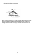
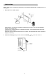
Quick Installation 1 Remove two rear panel covers 2 Connect power cord. 3 Connect video cable 5 Audio Installation (optional) Speakers Connect the audio cable (line color) to the AUDIO OUT port of your computer’s sound card, then to the LCD display’s AUDIO IN (line color) port (see illustration below).
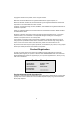
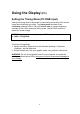
Using the Display (PC) Setting the Timing Mode (PC RGB Input) Setting the timing mode is important for maximizing the quality of the screen image and minimizing eye strain. The timing mode consists of the resolution (example 1280 x 768) and refresh rate (or vertical frequency; example 60 Hz). After setting the timing mode, use the OSD controls to adjust the screen image. NOTE: For the best picture quality set your LCD display timing mode to: 1280 x 768 @ 60Hz. To set the Timing Mode: 1.
PREPARATION Please, make sure to connect the power plug to the wall outlet socket after connecting the TV to the adapter! 1. Place the TV on a solid surface. Ensure that the TV is placed in a position to allow free flow of air. Do not cover the ventilation openings on the back cover. To prevent any unsafe situations, no naked flame sources, such as lighted candles, should be placed on or in the vicinity. Avoid heat, direct sunlight and exposure to rain or water.
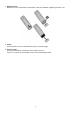
3. Remote control: Remove the cover of the battery compartment. Insert the 2 batteries supplied (Type AAA 1.5V). 4. Power: Insert the power cord in the wall socket having an AC power supply. 5. Turn the TV on: Press the power button at the bottom of the bezel to turn it on. If the TV is in power off, the indicator in front of the TV illuminates amber.
OPERATING INSTRUCTIONS USE OF THE REMOTE CONTROL POWER: Press to turn on/off the TV. The TV is never completely powered off unless it is physically unplugged. POWER Temporarily interrupt the sound or restore it. 3 2 1 CH 4 5 6 DISPLAY 7 8 9 100 0 Press this button to Display Channel number on the right-top corner. VOL PC 0~9/100 Digit buttons TV/VIDEO To select a TV channel.
TO USE THE MENUS 1. 2. 3. 4. Press the MENU button to display each menu Use the cursor up/down to select a menu item. Use the cursor left/right to enter a submenu or enable/disable the function. Press the MENU button to exit the menu. MAIN MENU Press the MENU button into the main OSD (On Screen Display). Adjust item include VIDEO ADJUST, AUDIO ADJUST, CLOSED CAPTION ,V-CHIP, SLEEP TIMER , SET UP and PC ADJUST. Video Adjust 1. 2. 3. 4. 5. Contrast, Brightness and Saturation are adjusted from 0 to 100.
When adjust any item sub-OSD will show up like this. Audio Adjust 1. 2. 3. Volume is adjusted from 0 to 100. Bass and Treble are adjusted from 0 to 100. W-Head Phone (optional) is the function for wireless headphone enable or disable. You can adjust audio Volume, Balance, Bass and Treble to the levels you prefer. When adjust any item sub-OSD will show up like this.
CLOSED CAPTION It’s allows you to read the dialog of television programs on the TV screen. Designed to help the hearing impaired, this feature uses on screen “ text boxes” to show dialogue and conversations while the TV program is in progress. Captions will appear on the screen only during captioned broadcasts. Remark: the captions do not always use correct spelling and grammar. Not all TV programs and product commercials are made for broadcast with Closed Caption information included.
V-CHIP SETUP Select V-Chip on OSD then enter 4 digits of pin number. Initial pin number is “0000”. If you enter an incorrect pin number “Incorrect” message will be displayed. It is the parental control function (V-chip). It is used to block program viewing based on the ratings by the broadcaster. The default setting is to allow all programs to be viewed. Viewing can be blocked by the type of program and by the categories chosen be blocked. It is also possible to block all program viewing for a time period.
C. Setting up Movie Guidelines Use Up/Down arrow buttons to move around the matrix and press Right arrow button to change the value from “U” to ‘B” or “B” to “U” D. CHANGE PIN Personal Identification Number is for change password to control the Vchip setup; it’s included three steps. ENTER PIN to enable this function, then ENTER NEW PIN to change a new one. After that COMFIRM NEW PIN.
Sleep Timer It is for set a time period after which the TV should switch itself to standby. The counter runs from 0 > 30 > 60 > 90 > 120 minutes. The timer begins to count down from the number of minutes selected after the display has disappeared. Note: To view the remaining time, press the SLEEP button once. To cancel the sleep time, repeatedly press the SLEEP button until… appears. If you turn the TV off after setting the sleep time, the setting will be erased. Set it again. Set up 1 1.
PC Adjust 1. 2. Auto Adjust is the function auto-sizing for VGA input. Contrast, Brightness, Focus, Clock, H-Position, V-Position and Color Temp are the functions for PC adjustment. - Color Temp for you can adjust the color temperature you prefer.
CONNECT PERIPHERAL EQUIPMENT FRONT PANEL CONTROL KNOBS Power Key: Press to turn on or off the TV. MENU Key: Press to show the OSD menu and exit OSD menu at the TV. Down / Up Key: Press to perform select function and channel. - / + Key: Press to confirm your function selection and adjustment. Source Key: Press to select your input source. There is a wide range of video and audio equipment that can be connected to your TV. The following connection diagrams show you how to connect them.
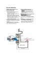
VIDEO RECORDER How to connect 1. Connect the antenna cable to the RF IN port of your VCR. 2. Connect another RF cable from the output RF of your VCR to the Antenna input of your TV. Better quality when playing from your VCR can be obtained if you also connect the Video, to the VIDEO, AUDIO L and R Audio LEFT AND right (only for stereo equipment) cables inputs AV. If you are using only mono equipment, connect only the VIDEO and the AUDIO L (Mono) ports.
CAMERA, CAMCORDER, VIDEO GAME SET, … How to connect 1. Composite Video: Connect your camera, camcorder, videogame set,… to Audio port (Audio L for mono) and Video port . 2. S-Video Connection S-VHS quality with an S-VHS camcorder is obtained by connecting the S-VHS cable with the S-VIDEO input and AUDIO input . How to use 1. 2. Select VIDEO or S-VIDEO input source (see P7 TV/ VIDEO) Turn on the external AV equipment. DVD PLAYER How to connect 1.
DIGITAL SET TOP BOX Connect DTV set top box RF output to TV Antenna input (TV channel set to CH3 or CH4). If your DTV set top box has component (Y, Pb, Pr) video ports, use them for better picture. How to connect component video: 1. Connect the three separate component video cables ports and to the Y, Pb and Pr ports on the TV. 2. to the DTV player’s AUDIO L and R ports and to the L and R Connect the audio cables AUDIO AV ports on the TV. to the DTV set-top box Y, Pb and Pr How to use 1. 2.
HEADPHONE 1. 2. 3. The earphone jack is located at the rear corner of the TV. The MUTE key on the remote control works on both internal speaker and the earphone. Use volume key to adjust the volume. Note: When a TV channel or external AV source is blocked because of a rating set via the Parental control menu, also the headphone is muted. TIPS Care of the screen Do not rub or strike the screen with anything hard as this may scratch, mar, or damage the screen permanently.
PRODUCT SPECIFICATION Feature 17” screen WXGA ( 1280 x 768 ) Resolution Wide Viewing Angle ( 170° H / 170° V ) Built-in 181 channel Tuner with MTS, SAP, Closed Caption & V-chip PC Input (Max. Resolution : 1280 x 768/60Hz) Items LCD Panel Specification Screen Size 17” TFT-LCD Panel Aspect Ratio 15:9 Resolution 1280 x 768 (WXGA) Display Area (opening) H x 372mm x 223mm V Pixel Pitch 0.291mm x 0.291mm Display colors 16.
Signal Input PC Input PnP compatibility Input frequency Recommended Input Audio Analog: D-Sub 15 pin (detachable cable) DDC 2B Analog: FH: 31.5KHz to 49KHz FV: 56Hz to 75Hz Analog: 1280 x 768 (60Hz) Headphone Mini-jack for stereo (3.5ø) Speaker (built-in): Two 5 watt speakers Headphone Mini-jack for stereo (3.
Compatibility Modes VESA VGA 640 x 480 60 31,5 60 31,5 VESA VGA 640 x 480 72 37,9 72 37,9 VESA VGA 640 x 480 75 37,5 75 37,5 VESA VGA 720 x 400 70 31,5 70 31,5 SVGA 800 x 600 60 37,9 60 37,9 SVGA 800 x 600 72 48,1 72 48,1 SVGA 800 x 600 75 46,9 75 46,9 VES A XGA 1024 x 768 60 48,4 60 48,4 VES AXGA 1024 x 768 75 60,0 75 60,0 MAC 16" 832 x 624 74,55 49,725 - - MAC 19" 1024 x 768 75 60,24 - - SVGA CVT SVGA CVT 1280x768 60 47.
BEFORE CALLING SERVICE Please make these simple checks before calling service. These tips may save you time and money since charges for receiver installation and adjustments of customer controls are not covered under your warranty.
Customer Support For technical support or product service, see the table below or contact your reseller. NOTE: You will need the product serial number. Country/ Region Web site T = Telephone F = FAX Email United States www.viewsonic.com/ support T: (800) 688-6688 F: (909) 468-1202 service.us@ viewsonic.com Canada www.viewsonic.com/ support T: (800) 688-6688 F: (909) 468-1202 service.ca@ viewsonic.com United Kingdom www.viewsoniceurope.com T: 0800 833 648 F: (01293) 643910 service.
GLOSSARY Audio / Video Inputs Located on the rear and the front of the receiver these connectors (RCA phono type plug) are used for the input of audio and video signals. Designed for use with VCRs (or other accessories) in order to receive higher picture resolution and offer sound connection options. Menu An on-screen listing of features shown on the TV screen is made available for user adjustments.
Limited Warranty VIEWSONIC LCD DISPLAY What the warranty covers: ViewSonic® warrants its products to be free from defects in material and workmanship during the warranty period. If a product proves to be defective in material or workmanship during the warranty period, ViewSonic will, at its sole option, repair or replace the product with a like product. Replacement product or parts may include remanufactured or refurbished parts or components.
Safety Guidelines Warning: This device must be operated with the original power supply, part number: 12VDC LSE9901B1250, 12VDC UP06031120. CAUTION: The socket-outlet should be installed near the equipment and should be accessible. CAUTION: Use a power cable that is properly grounded. Always use the appropriate AC cord that is certified for the individual country. Some examples are listed below: USA................UL Switzerland .... SEV Canada ..........CSA Britain............. BASE/BS Germany ........
ViewSonic Corporation