ViewSonic ® NMP-640 - User Guide Commercial Media Player Model No.
Compliance Information FCC Statement This device complies with part 15 of FCC Rules. Operation is subject to the following two conditions: (1) this device may not cause harmful interference, and (2) this device must accept any interference received, including interference that may cause undesired operation. This equipment has been tested and found to comply with the limits for a Class B digital device, pursuant to part 15 of the FCC Rules.
Important Safety Instructions 1. 2. 3. 4. 5. 6. 7. 8. 9. 10. 11. 12. 13. 14. 15. 16. 17. Do not use the equipment near water. Wipe the machine with a soft and dry cloth. Do not block any vent holes. Please install the product in accordance with the manufacturer’s instructions. Do not use the product on your legs for a long time because it gets hot and you may be burned. Please avoid installing the product in a place where the temperature is above 40°C or lower than 0°C, or in a place that is moist or wet.
Declaration of RoHS Compliance This product has been designed and manufactured in compliance with Directive 2002/95/EC of the European Parliament and the Council on restriction of the use of certain hazardous substances in electrical and electronic equipment (RoHS Directive) and is deemed to comply with the maximum concentration values issued by the European Technical Adaptation Committee (TAC) as shown below: Proposed Maximum Concentration Actual Concentration Lead (Pb) 0.1% < 0.1% Mercury (Hg) 0.
Copyright Information Copyright© ViewSonic Corporation, 2011. All rights reserved. ViewSonic, the three birds logo, OnView, ViewMatch, and ViewMeter are registered trademarks of ViewSonic Corporation. Disclaimer:ViewSonic Corporation shall not be liable for technical or editorial errors or omissions contained herein; nor for incidental or consequential damages resulting from furnishing this material, or the performance or use of this product.
Table of Contents Chapter 1 Introducing the NMP-640 Left/Right side View ............................................................................................ 2 Front Side View .................................................................................................. 2 Top Side View .................................................................................................... 3 Back Side View .........................................................................................
Chapter 1 Introducing the NMP-640 The NMP-640 Network Media Player is a compact and easy to use desktop. It features all the standard PC capabilities but with a slim body design which enables you to do spreadsheets, create documents, watch online content and browse the internet in a smarter and greener way.
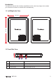
Introduction The NMP-640 features all the desktop capabilities but with a slim body design which enables you to browse the internet in a relaxed and comfortable way. 1-1 Left/Right side View 190.00mm 150.00mm 25.4mm 1-2 Front Side View No.
1-3 Top Side View No. Name Description 1 Microphone in Port Connects to a microphone 2 Headphone out Port Connects to headphones 3 USB2.0/e-SATA Combo Connects USB2.0 or e-SATA devices 4 Multi-Function Card Reader Support SD/MS/MS pro/MMC memory cards 1-4 Back Side View No. Name Description 1 Air vent For cooling system to let air flow in side the chassis 2 Kensington Lock Anti-theft lock 3 HDMI Port Connects to HDMI audio and video 4 USB 2.0 Port Connects to USB 2.
Chapter 2 Connecting Peripherals In this chapter, the placement and the connection of some necessary peripherals will be introduced.
2-1 Placement of the NMP-640 Network Media Player 1. On the Desk Seat the unit in the desktop stand as shown to the right. 2. Mounted to the back of a display This is the best space-saving way. 1.Use four screws(M4*10, round head) to fasten the VESA mounting bracket to the back of the display.
2. Fit the NMP-640 into the bracket with the power button located at the top for easy access. 3.Install top bar on the bracket.
2-2ConnectionofNMP-640 1. Connecting the NMP-640 to a monitor Connect to the monitor thru the VGA connector. 2.Connecting USB Devices Connect USB devices using the USB ports on the top or back, for example, mouse and keyboard. 3.Connecting the network cable Connect the LAN cable into the RJ-45 port with the other end connected to a hub or switch.
4.Connecting the power cord Connect the power adapter to the power input port of the NMP-640, and push the power button to start it up.
Chapter 3 BIOS Setup This chapter provides a description of the BIOS setup utility. The BIOS setup menus and available selections may vary from those of your product. For specific information on the BIOS for your product, please contact ViewSonic ® . The BIOS setup utility provides a built-in Setup program, which allows the user to modify the basic system configuration and hardware parameters.
MainMenu The BIOS Setup is accessed by pressing the button after the Power-On Self-Test (POST) memory test begins and before the operating system boot begins. Once you enter the BIOS Setup Utility, the Main Menu will appear on the screen. The Main Menu provides System Over-view information and allows you to set the System Time and Date. Use the “←” and “→” cursor keys to navigate between menu screens. ►SystemTime This item allows you to configure the desired time.
Advanced Menu ►Quick Boot If this item is set as Enabled, the system can be started within five seconds and some detection items will be ignored. The options are [Disabled] and [Enabled]. ►Quiet Boot To start the system quietly. (Full Screen Log display can be shut down) ►Onboard LAN Controller[Enabled] This item is used to enable or disable the Onboard LAN Controller. ►OnboardLANROM[Disabled] This item is used to enable or disable the Onboard LAN ROM.
Boot Menu ►BootDevicePriority Press to go to relative submenu. ►1stBoot Device These items are used to specify the boot sequence from the available devices. Security Menu ►ChangeSupervisorPassword Select this item to set or change the supervisor password. The Supervisor Password item on top of the screen displays the default Not Installed. After you have set a password, this item displays Installed.
►ChangeUser Password Select this item to set or change the user password. The User Password item on top of the screen displays the default Not Installed. After you have set a password, this item displays Installed. ►Clear User Password Select this item to delete the user password. Exit Menu ►Save Changes and Exit Exit system setup after saving the changes. Once you are finished making your selections, choose this option from the Exit menu to ensure the values you selected are saved to the CMOS RAM.
Chapter 4 Windows 7 Hard Disk Recovery Solution This chapter introduces the Windows 7 recovery · Using the recovery partition. Recovery partition contains a factory installed operating system, drivers and other applications of the image file. The recovery partition can quickly restore your computer to its original state, so that your hard disk can operate in the best condition. Please backup your data files (such as Outlook PST file) to the other disk before using the recovery partition.
Plan A — Advanced Startup Options: 1. Turn on the master computer. 2. Press F8 before Windows starts. 3. Choose “Repair Your Computer”. Note: If Windows starts, you did not press F8 within the appropriate time allows. Shutdown the computer and try again. 4. From the System Recovery Options dialog box, select a language and keyboard layout.
5. Select the user you created and enter your password. 6. Select Reinstall Windows.
7. Click the Yes button to start the reinstallation of Windows using the image you placed in the recovery partition. Plan B — Recovery Console: 1. On the master computer, remove the DVD-ROM and USB hard drive and start the computer. 2. Execute Sysprep with the OOBE option and restart the PC. 3. Start the destination computer and complete the Out of Box Experience (OOBE). 4. Press the Start Button and in the search input area, type "Recovery".
5. From the search results, launch the Recovery control applet. 6. Select the "Advanced recovery methods" option. 7. Select "Reinstall Windows" option.
8. Follow the on-screen instructions if you want to back up your files. Then the computer will restart.
9. Verify that the computer starts in Windows RE. 10. From the System Recovery Options dialog box, select a language and keyboard layout.
11. Click the Yes button to reinstall Windows using the image you placed in the recovery partition. Note: By selecting Yes, Windows will begin the reinstallation of Windows using the recovery image you created.
12. Once the Windows Setup is complete, the PC will boot to OOBE. Complete Windows Welcome. Note: If you create a backup prior to the restore, you'll have the option to restore the backup. Note: Restore the system will not completely remove all data on the original disk, the system will automatically save the user files to the “Windows.old” folder, this folder can be deleted after confirmed useless. Appendix-FrequentlyAskedQuestions Q1: Is the HDD designed to be shock proof? A1: Yes it is.
Customer Support For technical support or product service, see the table below or contact your reseller. Note: You will need the product serial number. Country/ Region Web Site T=Telephone F=Fax Australia/New Zealand www.viewsonic.com.au Canada www.viewsonic.com Europe www.viewsoniceurope.com www.viewsoniceurope.com/uk/support/call-desk/ Hong Kong www.hk.viewsonic.com T= 852 3102 2900 service@hk.viewsonic.com India www.in.viewsonic.com T= 1800 11 9999 service@in.viewsonic.
Limited Warranty VIEWSONIC Media Player What the warranty covers: ViewSonic warrants its products to be free from defects in material and workmanship, under normal use, during the warranty period. If a product proves to be defective in material or workmanship during the warranty period, ViewSonic will, at its sole option, repair or replace the product with a like product. Replacement product or parts may include remanufactured or refurbished parts or components.