PJ1065 User Guide Guide de l’utilisateur Bedlenungsanleltung Guía del usuario Guida Dell’utente Användarhandbok Käyttöopas 使用者指南 使用者指南 Image Size 30” – 300” XGA LCD Projector
Contents For Your Records ............................................................................................. 1 FEATURES BEFORE USE Contents of Package ........................................................................................ 2 Part Names....................................................................................................... 3 Inserting the Batteries.......................................................................................
Copyright © ViewSonic Corporation, 2002. All rights reserved. Macintosh, Mac and Power Macintosh are registered trademarks of Apple Computer, Inc. Microsoft, Windows, Windows NT, and the Windows logo are registered trademarks of Microsoft Corporation in the United States and other countries. ViewSonic, the three birds logo and OnView are registered trademarks of ViewSonic Corporation. VESA and SVGA are registered trademarks of the Video Electronics Standards Association. DPMS and DDC are trademarks of VESA.
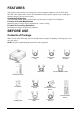
FEATURES This liquid crystal projector is used to project various computer signals as well as NTSC/PAL/ SECAM video signals onto a screen. The installation of this projector requires only a small space, and large images can be projected easily. Outstanding Brightness The UHB lamp and the highly efficient optical system assure a high level of brightness. Function for Partial Magnification Interesting parts of images can be magnified for a closer viewing.
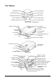
Part Names FOCUS Button ZOOM Button KEYSTONE Button INPUT Button STANDBY/ON Button MENU Button RESET Button LAMP Indicator TEMP Indicator POWER Indicator Control Panel (refer to page 9, “OPERATIONS”) Control panel Remote control sensor Lens Ventilation openings (exhaust) Filter Cover (air filter) Carrying Handle Foot adjuster Filter cover (air filter and intake for the cooling fan) Lens cap Front/right view Remote control sensor Foot adjuster Terminal panel (see below) Speaker Power swi
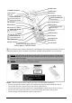
BLANK Button STANDBY/ON Button LASER Button VIDEO Button Disk pad RGB Button MOUSE/RIGHT Button Used to operate the mouse shift function and left-click function. Used to click the right mouse button. AUTO Button KEYSTONE Button MENU Button RESET Button MENU SELECT Button Used to click the left mouse button. Button Used to operate the mouse shift function. Used to click the right mouse button.
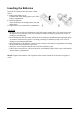
Inserting the Batteries Insert the AA batteries into the remote control device. 1 Remove the battery cover. Push the knob while lifting up the cover of the battery compartment. 2 Insert the batteries. Insert the batteries according to their plus and minus poles. 3 Replace the cover to the battery compartment. CAUTION • Be sure to only use the specified batteries with this remote control device.
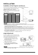
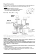
INSTALLATION Installation of the Projector and Screen To set the screen size and projection distance, see the illustration and table below. The projection distance shown in the table below Screen indicates the full size (1024 × 768 dots). a:Distance from the projector to the screen (± 10%). b:Distance from the lens center to the bottom of the screen (± 10%). Table 1: Reference for Installation Screen size [inches (m)] 40 (1.0) 60 (1.5) 80 (2.0) 100 (2.5) 120 (3.0) 150 (3.8) 200 (5.0) a [inches (m)] Min.
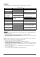
Cabling Refer to the table below for connecting each terminal of the projector to each device. Table 2: Cabling Terminal Function Cable Analog RGB output RGB IN 1 RGB IN 2 RGB OUT Accessory or optional RGB cable with Dsub 15-pin shrink jack and inch thread screws.
Power Connection Be sure to use the correct supplied power cords depending on the power outlet to be connected to. Connect the AC inlet of the projector firmly to the power outlet with the power cord. CAUTION • Be careful when you handle the power cord. • Firmly connect the power cord. Do not use a loosened or unsafe power outlet or a malfunctioning contact.
OPERATIONS POWER Indicator STANDBY/ON Button STANDBY/ ON Button ZOOM button FOCUS button Power Switch FOCUS button Lens cap ZOOM button Power ON 1 Check if the power cord is connected correctly. 2 Set the power switch to [I]. When the standby mode is selected, the POWER indicator is orange. 3 Press the STANDBY/ON button on the control panel or the remote control device. The warm-up starts and the POWER indicator blinks green.
Basic Operation The basic operations shown in Table 3 can be performed with the supplied remote control device or by way of the projector’s control panel. Items indicated by (*) may be used from the control panel. Table 3: Basic Operation Item Description INPUT SELECT Select Input Signal (*): Press the INPUT button. RGB IN 1→RGB IN 2→DVI →VIDEO→S-VIDEO→COMPONENT VIDEO (→RGB IN 1) Select RGB Input: Press the RGB button.
Items indicated by (*) may be used with the control panel. Table 3: Basic Operation (continued) Item Description VOLUME Volume Adjustment: Press the VOLUME MUTE Set/Clear Mute Mode: Press the MUTE button. No sound is heard in the MUTE mode. AUTO Automatic Adjustment at RGB Input: Press the AUTO button. Horizontal position(H. POSIT), vertical position (V. POSIT), clock phase (H. PHASE), and horizontal size(H. SIZE) are automatically adjusted.
Setup Menu The following adjustments and settings are possible when SETUP is selected at the top of the menu. Part of the Setup menu differs between RGB input and video input. Select an item with the and buttons, and start operation. Use the Single menu to reduce menu size (see Table 3, MENU SELECT).
Input Menu The following functions are available when INPUT is selected on the menu. Select an item with the and buttons, and start or stop operation with the and buttons. The function indicated (**) are effective on video input mode, the P.IN P. window on RGB input mode. Table 5: Input Menu Item Description AUTO Automatic Adjustment at RGB Input: Select the EXECUTE with the button. Horizontal position (H.POSIT), vertical position (V.POSIT), clock phase (H.PHASE), and horizontal size (H.
Image Menu The following adjustments and settings are available when IMAGE is selected on the menu. Select an item with the and buttons, and start or stop operation with the and buttons. Table 6: Image Menu Description Item BLANK Select Blank Screen: Select the screen with the / button. The selected one (MyScreen, ORIGINAL or one colors) is displayed when the BLANK mode is ON. MyScreen is a mode that the customer-customized screen is displayed. This is the blue screen at the factory setting.
Options Menu The following adjustments and settings are available when OPT. is selected on the menu. Select an item with the and buttons, and start operation. Table 7: Options Menu Item Description VOLUME Volume Adjustment: Reduce VOLUME MENU COLOR Select Menu Background Color: Select with the and buttons. LANGUAGE Operation Start/Stop: Press the button. Select Menu Display Language: Select with the and buttons. AUTO OFF Operation Start/Stop: Press the button.
No Signal Menu The same adjustments and settings are available as with the Image and Options menus when the MENU button is pressed during display of the “NO INPUT IS DETECTED ON***”or “SYNC IS OUT OF RANGE ON***”message while no signal is received. Table 8: No Signal Menu Description Item VOLUME Volume Adjustment: Reduce VOLUME Increase VOLUME • When this function is used, audio input is automatically switched to video.
MAINTENANCE Lamp HIGH VOLTAGE HIGH TEMPERATURE HIGH PRESSURE Contact your dealer before replacing the lamp. For the lamp replacement, see the item “Optional Parts” of the Table 12. Before replacing the lamp, switch power OFF, remove the power cord from the power outlet, and wait approximately 45 minutes until the lamp has cooled. The lamp may explode if handled at high temperatures. WARNING: • • • • For disposal of used lamp, treat according to the instruction of community authorities.
Replacing the Lamp 1 Switch the projector OFF, remove the power cord from the power outlet, and wait at least 45 minutes for the unit to cool. 2 Prepare a new lamp. 3 Check that the projector has cooled sufficiently, and gently turn it 4 5 6 7 8 upside down. Loosen the screw as shown in the diagram, and remove the lamp cover. Loosen the two screws, and gently remove the lamp while holding the grips. Touching the inside of the lamp case may result in uneven coloring.
Air Filters Cleaning Air Filters filter cover This projector uses 2 air filters. These air filters should be cleaned as described below at intervals of approximately 100 hours. 1 Switch the projector power supply OFF, and remove the power cord from the power outlet. 2 Remove the filter cover and the air filter. 3 Clean the air filter with a vacuum cleaner. 4 Set the air filter and the filter cover.
TROUBLESHOOTING OSD Message The messages as described below may appear on the screen at power ON. Take the appropriate measures when such messages appear. Table 9: OSD Message Message Contents CHANGE THE LAMP AFTER REPLACING LAMP, RESET THE LAMP TIME. (*1) The usage time of lamp will be reaching 2000 hr shortly (*2). It is recommended to replace the lamp soon. Prepare a new lamp as replacement. CHANGE THE LAMP AFTER REPLACING LAMP, RESET THE LAMP TIME. THE POWER WILL TURN OFF AFTER **hr.
Indicator Message The POWER indicator, LAMP indicator, and TEMP indicator are lit and blank as follows. Take the appropriate measures. Table 10: Indicator Message POWER indicator LAMP indicator TEMP indicator Lit orange Turns off Turns off The Standby mode has been set. Blinks green Turns off Turns off Warming up. Please wait. Lit green Turns off Turns off ON. Normal operation possible. Blinks orange Turns off Turns off Cooling down. Please wait. Turns off Lamp is not lit.
Symptom Before requesting repair, please check in the following chart. If the situation cannot be corrected, then contact your dealer. Table 11: Symptom Symptom The power is not turned on. No video or audio. Video is present but no audio. Audio is present but no video. Colors are pale and color matching is poor. Images are dark. Video is blurred. 22 Possible cause Remedy Page The main power switch is not turned on. Turn on the main power switch. The power cord is disconnected.
SPECIFICATIONS Table 12: Specifications Item Panel size Liquid crystal Drive system projector Pixels Lens Lamp Speaker Power supply Power consumption Temperature range Size Weight (mass) Specification 1 RGB IN RGB signal input 2 DVI AUDIO IN RGB1 DVI RGB2 Y CB/PB CR/PR 0.7 Vp-p, 75 Ω Terminator (positive) S-VIDEO COMPONENT VIDEO AUDIO RGB OUT Signal output AUDIO OUT Control functions Optional parts CONTROL USB 200m Vrms, 50 kΩ (max. 3.0Vp-p) Stereo mini jack 1.
Customer Support For technical support or product service, see the table below or contact your reseller. NOTE: You will need the product serial number. Country/Region Web site T = Telephone F = FAX Email United States viewsonic.com/support T: (800) 688-6688 F: (909) 468-1202 service.us@ viewsonic.com Canada viewsonic.com/support T: (800) 688-6688 F: (909) 468-1202 service.ca@ viewsonic.com United Kingdom viewsoniceurope.com T: 0800 833 648 F: (01293) 643910 service.eu@ viewsoniceurope.
LIMITED WARRANTY VIEWSONIC Projector What the warranty covers: ViewSonic® warrants its products to be free from defects in material and workmanship during the warranty period. If a product proves to be defective in material or workmanship during the warranty period, ViewSonic will at its sole option repair or replace the product with a like product. Replacement product or parts may include remanufactured or refurbished parts or components.
Appendix Power Cord Safety Guidelines Caution: Use a power cable that is properly grounded. Always use an AC power cord that meets your country’s safety standard. USA .............................. UL Canada......................... CSA Germany....................... VDE Switzerland ...................SEV Britain............................BASE/BS Japan ............................
FCC Information This equipment has been tested and found to comply with the limits for a Class B digital device, pursuant to part 15 of the FCC Rules. These limits are designed to provide reasonable protection against harmful interference in a residential installation. This equipment generates, uses, and can radiate radio frequency energy, and if not installed and used in accordance with the instructions, may cause harmful interference to radio communications.
ViewSonic Corporation