ViewSonic ® Pro8450w DLP Projector - User Guide - Guide de l’utilisateur - Bedienungsanleitung - Guía del usuario - Guida dell’utente - Guia do usuário - Användarhandbok - Käyttöopas - Руководство пользователя - 使用手冊 (繁體) - 使用手册 (简体) IMPORTANT: Please read this User Guide to obtain important information on installing and using your product in a safe manner, as well as registering your product for future service.
Compliance Information FCC Statement This device complies with part 15 of FCC Rules. Operation is subject to the following two conditions: (1) this device may not cause harmful interference, and (2) this device must accept any interference received, including interference that may cause undesired operation. This equipment has been tested and found to comply with the limits for a Class B digital device, pursuant to part 15 of the FCC Rules.
Important Safety Instructions 1. Read these instructions. 2. Keep these instructions. 3. Heed all warnings. 4. Follow all instructions. 5. Do not use this unit near water. 6. Clean with a soft, dry cloth. 7. o not block any ventilation openings. Install the unit in accordance with the D manufacturer’s instructions. 8. Do not install near any heat sources such as radiators, heat registers, stoves, or other devices (including amplifiers) that produce heat. 9.
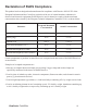
Declaration of RoHS Compliance This product has been designed and manufactured in compliance with Directive 2002/95/EC of the European Parliament and the Council on restriction of the use of certain hazardous substances in electrical and electronic equipment (RoHS Directive) and is deemed to comply with the maximum concentration values issued by the European Technical Adaptation Committee (TAC) as shown below: Proposed Maximum Concentration Actual Concentration Lead (Pb) 0.1% < 0.1% Mercury (Hg) 0.
Copyright Information Copyright© ViewSonic® Corporation, 2010. All rights reserved. Macintosh and Power Macintosh are registered trademarks of Apple Inc. Microsoft, Windows, Windows NT, and the Windows logo are registered trademarks of Microsoft Corporation in the United States and other countries. ViewSonic, the three birds logo, OnView, ViewMatch, and ViewMeter are registered trademarks of ViewSonic Corporation. VESA is a registered trademark of the Video Electronics Standards Association.
CONTENTS Introduction ...................5 Ceiling mount installation ...............59 Projector Features ............................ 5 Package Contents ............................ 6 Projector Overview ........................... 8 Appendix ..................... 60 Using the Product .......10 Control Panel ................................. 10 Connection Ports ............................ 11 Remote Control .............................. 13 Installing the Batteries ....................
Introduction Projector Features The projector integrates high-performance optical engine projection and a user - friendly design to deliver high reliability and ease of use. The projector offers the following features: Single chip 0.65" Texas Instruments DLP® technology WXGA (1280 x 800 pixels) Auto image re-sizing (Auto-Sync.) to 1280 x 800 full screen with scaling compression compatibility for VGA, SVGA, XGA, SXGA and WXGA.
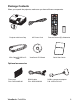
Package Contents When you unpack the projector, make sure you have all these components: Projector with Lens Cap AC Power Cord Remote Control (IR) & batteries VGA Cable (D-SUB to DSUB) ViewSonic CD Wizard Quick Start Guide Optional accessories Filter cover P/N: P4R34-4600-00 ViewSonic Pro8450w RS232 cable P/N: J2552-0208-00 RGB to component adapter P/N: J2552-0212-00 6
Projector Carrying Case Contact you dealer immediately if any items are missing, appear damaged, or if the unit does not work. Save the original shipping carton and Packing material; they will come-in handy if you ever to ship your unit. for maximum protection, repack your unit as it was originally packed at the factory.
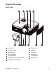
Projector Overview Front View 13 1 12 2 3 4 11 5 10 9 7 6 1 Lens cap 8 Filter cover 2 Elevator button 9 Speaker 3 Elevator foot 10 Focus ring 4 Lens cap strap 11 Zoom ring 5 Projection lens 12 Control panel 6 Front IR remote control sensor 13 Lamp cover 7 Ventilation holes (intake) ViewSonic Pro8450w 8 8
Rear View 1 1 2 3 2 4 5 6 5 2 3 4 5 6 Connection ports AC power socket Kensington lock Rear IR remote control sensor Speaker Ventilation holes (exhaust) Bottom View 3 1 2 1 2 3 Ceiling mount holes (M4*8) Tilt-adjustment feet Security bar This projector can be used with a ceiling mount for support. The ceiling mount is not included in the package. Contact your dealer for information to mount the projector on a ceiling.
Using the Product Control Panel 9 1 2 3 4 8 5 6 10 11 6 7 1 2 3 4 5 6 7 8 9 10 11 4 Power (Power LED indicator) Refer to “LED Indicator Messages”. TEMP (Temperature LED indicator) Refer to “LED Indicator Messages”. LAMP (Lamp LED indicator) Refer to “LED Indicator Messages”. Keystone/Arrow keys ( /Up, /Down) Manually correct distorted images resulting from an angled projection. Four directional buttons Use four directional buttons to select items or make adjustments to your selection.
Connection Ports 1 2 3 4 5 6 7 8 9 10 11 1 2 18 17 3 4 16 15 5 6 7 8 9 14 13 12 11 10 RS-232 When operating the projector via a computer, connect this to the controlling computer's RS-232C port. Monitor Out Connect to a computer display, etc. Component (Y Cb/Pb Cr/Pr) Connect Y Cb/Pb Cr/Pr output from video equipment to this jack. S-Video Connect S-Video output from video equipment to this jack. Service This connector is for firmware update and mouse function support.
12 13 14 15 16 17 18 Audio Out Connect to a speaker or other audio input equipment. Audio 2 Connect an audio output from video equipment or computer to this jack. Audio 1 Connect an audio output from video equipment or computer to this jack. Audio 3 (L/R) Connect an audio output from video equipment to this jack. Video Connect composite video output from video equipment to this jack. Computer in 2 Connect image input signal (analog RGB or component) to this jack.
Remote Control 1 2 3 4 5 6 7 8 9 10 11 12 Power Turn the projector on or off. VGA Switch input source to Computer in 1 (analog RGB or component)/ Computer in 2 (analog RGB or component) by sequence. Source/Page up Display the source selection bar. Perform page up function when mouse mode is activated. Up/+, Down/When Magnify or Volume button is activated, use them to adjust the values.
17 18 19 20 21 22 23 24 25 Enter/ Left mouse Confirmed selections. Perform the left button of the mouse when mouse mode is activated. Right/ Lock When the On-Screen Display (OSD) menu is activated, the #4, #5, and #18 keys are used as directional arrows to select the desired menu items and to make adjustments. Activate panel key lock. ESC/ Right mouse Leave current page or items or to close OSD. Perform the right button of the mouse when mouse mode is activated. Volume Adjust the volume level.
Installing the Batteries 5. Open the battery cover in the direction shown. 6. Install batteries as indicated by the diagram inside the compartment. 7. Close the battery cover into position. Caution Risk of explosion if battery is replaced by an incorrect type. Dispose of used batteries according to the instructions. Make sure the plus and minus terminals are correctly aligned when loading a battery. Keep the batteries out of the reach of children.
Remote Control Operation Point the remote control at the infrared remote sensor and press a button. Operating the projector from the front 30 6m 5m m 8 7m 6m 15 Operating the projector from the rear 15 30 6m 8m 6m Do not point the laser directly to the people's eyes (especially small children). There is a danger of injury to the eyes. The remote control may not operate when there is sunlight or other strong light such as a fluorescent lamp shining on the remote sensor.
Connection When connecting a signal source to the projector, be sure to: 1. 2. 3. Turn all equipment off before making any connections. Use the correct signal cables for each source. Ensure the cables are firmly inserted.
Connecting a computer or monitor Connecting a computer The projector provides two VGA input sockets that allow you to connect them to both IBM® compatibles and Macintosh® computers. A Mac adapter is needed if you are connecting legacy version Macintosh computers. To connect the projector to a notebook or desktop computer: 1. 2. 3. Take the supplied VGA cable and connect one end to the D-Sub output socket of the computer.
Connecting Video source devices You can connect your projector to various Video source devices that provide any one of the following output sockets: Component Video S-Video Video (composite) You need only connect the projector to a Video source device using just one of the above connecting methods, however each provides a different level of video quality.
Connecting a Component Video source device Examine your Video source device to determine if it has a set of unused Component Video output sockets available: If so, you can continue with this procedure. If not, you will need to reassess which method you can use to connect to the device. To connect the projector to a Component Video source device: 1. 2.
Important If the selected video image is not displayed after the projector is turned on and the correct video source has been selected, check that the Video source device is turned on and operating correctly. Also check that the signal cables have been connected correctly.
Operation Powering On/Off the Projector Powering On the Projector: 1. 2. 3. 4. Remove the projector lens cap. Complete the AC power cord and peripheral signal cable(s) connections. Press to turn on the projector. The projector takes a minute or so to warm up. Turn on your source (computer, notebook, DVD, etc.). The projector automatically detects your source.
Adjusting the Projector Height Tilt-adjustment feet Elevator foot Elevator button The projector is equipped with an elevator foot to adjust the image height. To raise or lower the image: 1. 2. To raise or lower the image, press the elevator button and raise or lower the front of the projector. Release the button to lock the adjustment. To level the image on the screen, turn the tilt-adjustment feet to fine-tune the height.
Adjusting Projection Image Size Refer to the graphic and table below to determine the screen size and projection distance. Maximum zoom Minimum zoom Screen Center of lens Vertical offset Projection distance 16 : 10 Screen Projection distance [inch (m)] Screen size Diagonal [inch (cm)] (min. zoom) (max. zoom) 30 (76) 40 (102) 50 (127) 60 (152) 80 (203) 100 (254) 120 (305) 150 (381) 200 (508) 220 (559) 250 (635) 300 (762) 36 (0.91) 49 (1.23) 61 (1.55) 74 (1.88) 99 (2.52) 124 (3.16) 150 (3.
Locking control keys With the control keys on the projector locked, you can prevent your projector settings from being changed accidentally (by children, for example). When the Panel Key Lock is on, no control keys on the projector will operate except Power. 1. 2. Press on the projector or remote control. A confirmation message is displayed. Select Yes to confirm. To release panel key lock, press and hold for 3 seconds on the projector.
Setting the presentation timer The presentation timer can indicate the presentation time on the screen to help you achieve better time management when giving presentations. Follow these steps to utilize this function: 1. 2. 3. Go to the Setting > Presentation Timer menu and press MODE/ENTER to display the Presentation Timer page. Highlight Timer Period and decide the timer period by pressing / .
To cancel the timer, perform the following steps: 1. 2. 3. Go to the Setting > Presentation Timer menu and highlight Off. Press MODE/ENTER. A confirmation message displays. Highlight Yes and press MODE/ENTER to confirm. You will see the message “Timer is Off!” displaying on the screen.
Menu Operation The projector has multilingual on-screen display menus that allow you to make image adjustments and change a variety of settings. Color Temp.
Top-Left, Top-Right, Center, Bottom-Left, Bottom-Right Setting Front-Table, Front-Ceiling, Rear-Table, Rear-Ceiling 0 - 60 Filter Mode*2 High Altitude OSD Transparency Presentation Timer 0, 10, 20, 30, 40, 50, 60, 70, 80, 90 Timer Period Timer Display 0 - 240 Min Always, 1 Min, 2 Min, 3 Min, Never Timer Position Top-Left, Bottom-Left, Top-Right, Bottom-Right Timer Counting Direction Count Down, Count Up Black, Red, Green, Blue, Cyan, Yellow, Magenta, White Input Password Password Delete Start
NetWork Wired LAN Status Disconnect, Connect On, Off Default Gateway DNS Apply Wireless LAN Status Disconnect, Connect SSID SSID Display Connection Mode On, Off AP, Infrastructure On, Off Apply Network Restart Information Input Source Yes, No Computer 1, Computer 2, Component, Composite, S-Video, HDMI, USB 1, USB 2 MAC Address Filter Hours*2 Filter Hours Reset*2 Lamp Hours Lamp Hours Reset Factory Default *1 Adjustable range and default setting vary depending on signal type.
How to operate 1. 2. 3. 4. 5. 6. Press MENU on the projector or Menu on the remote control to open the OSD menu. When OSD is displayed, use / to select any feature in the main menu. After selecting the desired main menu item, press X to enter sub-menu for feature setting. Use / to select the desired item and adjust the settings with / . Press MENU on the projector or Menu on the remote control, the screen will return to the main menu.
Aspect Ratio Select how the picture fits on the screen: Auto : Scales an image proportionally to fit the projector's native resolution in its horizontal or vertical width. 4:3 : Scales an image so that it is displayed in the center of the screen with a 4:3 aspect ratio. 16:9 : Scales an image so that it is displayed in the center of the screen with a 16:9 aspect ratio. 16:10: Scale an image so that it is displayed in the center of the screen with a 16:10 aspect ratio.
Sharpness: Sharpen or soften the image. Tint: Shift colors toward red or green. Audio Setting Allow you to enter the Audio Setting menu. Computer 1: Select the audio input for Computer in 1 signal. When Audio in 1 is turned on, Audio in 2 and Audio in 3 will turn off automatically. Computer 2: Select the audio input for Computer in 2 signal. When Audio in 2 is turned on, Audio in 1 and Audio in 3 will turn off automatically. Video Source: Select the audio input for video source.
Auto Source Automatically scan through all the input sources. ECO Mode Use this function to dim the projector lamp light output which will lower power consumption and increase lamp life. This function will be unavailable when the DCR function is on. Filter Mode Use this function to activate filter mode after the projector is installed an optional filter cover. High Altitude Use this function to allow the fans operates at full speed continuously to achieve proper high altitude cooling of the projector.
Enable this function when power consumption is under 1W. DC 12V Enable or disable to trigger external devices such as anelectric screen. Others Allow you to enter the Others menu. Zoom: Zoom in and out the images. DCR (Dynamic Contrast Ratio): Enable DCR will further enhance contrast ratio by darkening the black scenes. Disable DCR will resume to normal contrast performance. DCR will impact lamp life and system noise performance.
be used when DHCP is set to No. The Subnet Mask “0.0.0.0” is prohibited. Default Gateway: A server (or router) to communicate across networks (subnets) that are divided by Subnet Mask. This function can only be used when DHCP is set to No. DNS: Setup DNS server address when DHCP is disable. Apply: Save and execute the wired LAN settings. Wirless LAN Allow you to configure the wireless LAN settings. Status: Display the projector’s status. SSID: Display the projector’s SSID information.
Resolution Display current input source resolution. H. Frequency Display current image horizontal frequency. V. Frequency Display current image vertical frequency. MAC Address Abbreviation for Media Access Control Address. MAC Address is a unique ID number assigned to each network adapter. Filter Hours Display the filter’s elapsed operating time (in hours). When Filter Mode is turned on, the Filter Hours also turns on automatically. Filter Hours Reset Reset the filter Hour to 0 hours.
Controlling the projector through a LAN environment You can manage and control the projector from one or more remote computers when they are properly connected to the same local area network. Wired connection Internet IP Router If you are in a DHCP environment: 1. Take a RJ45 cable and connect one end to the RJ45 LAN input jack of the projector and the other end to the RJ45 port on your Ethernet or router. 2.
4. 5. 6. 7. 8. Press to select the item you want to modify and press ENTER on the projector or Enter on the remote control. Press / to move the cursor and the enter the value. To save the settings, press ENTER on the projector or Enter on the remote control. If you do not want to save the settings, press MENU/EXIT on the projector or Menu on the remote control. Press to highlight Apply and press ENTER on the projector or Enter on the remote control.
Wireless connection ViewSonic wireless dongle To connect to the projector wirelessly, you have to plug a ViewSonic wireless dongle (optional) to the USB Type A connector on the projector, and then only a few OSD configuration steps are required. 1. 2. 3. 4. 5. 6. Make sure the projector is turned on. Press MENU/EXIT on the projector or Menu on the remote control and then press / until the NetWork menu is highlighted. Highlight Wireless LAN and press ENTER on the projector or Enter on the remote control.
Controlling the projector through a web browser Once you have the correct IP address for the projector and the projector is on or in standby mode, you can use any computer that is on the same local area network to control the projector. Important If you are using Microsoft Internet Explorer, make sure it is version 7.0 or higher. The screenshots in this manual are for reference only, and may differ from the actual design. 1.
7. To have access to the Admin page, you need to enter a password. The default password is “0000”. System Status: Displays the system information. General Setup: Allows you to change the password for the Admin page. Picture Setup/Image Setup: Provides some OSD menu items for adjusting the projected pictures. Alert Setup/SMTP Mail Setup: Allows you to setup the mail server and send system error messages to your ITS administrator. Network Setup: Provides wired and wireless network settings.
8. The Crestron (eControl) page displays the Crestron eControl user interface. The eControl page provides a variety of virtual keys to control the projector or adjust the projected pictures. i i ii You can press W/X to reveal more buttons. i iii i. These buttons function the same as the ones on the OSD menus or remote control. ii. To switch between input signals, click on your desired signal. iii.
The tools page allows you to manage the projector, configure the LAN control settings and secure access of remote network operation on this projector. iv vi viii v vii ix x iv. This section is only used with the Crestron Control System. Please contact Creston or refer to its user manual for setup information. v. Click the down arrow to reveal a drop down list and select a default language. vi. You can name the projector, keep track of its location and the person in charge of it. vii.
Please pay attention to the limitation of input length (including space and other punctuation keys) in the list blow: Category Item Crestron Control Projector Network Configuration User Password Admin Password ViewSonic Pro8450w Input Length IP Address IP ID Port Projector Name Location Assigned To DHCP (Enabled) IP Address Subnet Mask Default Gateway DNS Server Enabled New Password Confirm Enabled New Password Confirm Maximum Number of Characters 15 2 5 10 9 9 (N/A) 15 15 15 15 (N/A) 20 2 (N/A) 20 2
The info page displays the information and status of this projector. Press Exit to go back to the remote network operation page. After pressing the button “Contact IT Help”, the HELP DESK window will appear in the upper right corner of the screen. You will be able to deliver messages to RoomView software administrators/users who connect to the same local area network. For more information, visit http://www.crestron.com & www.crestron.com/getroomview.
Displaying images through pwPresenter Downloading and installing pwPresenter The pwPresenter is an application running on the host PC. It helps connect your computer to an available network projector and transfer the desktop content to the network projector via local network connection. 1. 2. 3. 4. Enter the main page of Network Control. See steps 1-2 on page 41 for details. Download pwPresenter. When the download is complete, install the software to your computer by clicking the exe file.
2. The Capture screen allows you to start or pause capture screen. 3. You can choose a capture mode from here. i ii iii i. ii. iii. To display a full screen, click FullScreen. To display a partial screen, click FixedSize. A square appears on your screen. You can place it where you want to project. If you wish to change the square, click Alterable.
4. The Basic Setting page allows you to configure pwPresenter. i ii iii iv v i. ii. iii. iv. v. To change the pwPresenter interface language, click the down arrow to reveal a drop-down list and select a desired language. Click Apply. Users can change the size parameters of the frame in FixedSize capture mode by modifying width and height on this page and click Apply to make changes take effect. User can use the mirror driver for presenter capture image, if the system has installed the mirror driver.
5. The Advanced Setting page allows you to configure pwPresenter. i ii iii i. ii. iii. To adjust the image quality, click the down arrow to reveal a drop-down list and select a desired quality level. Click Apply. To adjust the capture rate, move the slide bar. The network bandwidth may also affect the performance. Network port setting for fixed or manual type.
6. Network Display Management displays the Device Management and pwPresenter Management information. Device Management allows you to change device settings. i iii ii iv v i. ii. iii. iv. v. Click to change display port allows you to select display location of screen. Change password allows you to change password for the user type. Disconnect allows you to disconnect the projector from network. Access device via webpage allows you to access ViewSonic webpage control system.
pwPresenter Management allows you to select which computer to be connected and transfer the desktop content to the network projector. 7. Disconnect allows you to disconnect from the projector(s) by clicking the Disconnect icon. Important Be sure to turn off other virtual network control programs before using pwPresenter.
Displaying pictures with a USB storage device The built-in the ImageViewer application can display packaged images on a USB storage device (e.g. USB flash drive, and USB disk), a digital camera, or other device. You can connect a USB storage device to your projector. 1. 2. 3. Take a USB cable and connect the larger end to the USB A socket on the projector, and smaller end to the USB port of the device. If you are using a USB flash drive, connect it directly to the USB A socket.
Thumbnail/Slide show/Display: Display thumbnails, start the slide show or display the selected image. Name Order/Extend Order/Size Order/Time Order: Select the order setting by file/folder name, extended file name, image size or time. EXIF ON/EXIF OFF: Display the Exif information of the image or not. File Name On/File Name Off: Display the file name or not.
Maintenance The projector needs proper maintenance. You should keep the lens clean as dust, dirt or spots will project on the screen and diminish image quality. If any other parts need replacing, contact your dealer or qualified service personnel. When cleaning any part of the projector, always switch off and unplug the projector first. Warning Never open any of the covers on the projector. Dangerous electrical voltages inside the projector can cause severe injury.
Replacing the Lamp As the projector operates over time, the brightness of the projector lamp gradually decreases and the lamp becomes more susceptible to breakage. We recommend replacing the lamp if a warning message is displayed. Do not attempt to replace the lamp yourself. Contact the qualified service personnel for replacement. The lamp is extremely hot right after turning off the projector. If you touch the lamp, you may scald your finger.
1. 2. 3. 4. 5. 6. 7. 8. 9. Turn off the projector. If the projector is installed in a ceiling mount, remove it Unplug the power cord. Loosen the screw in the side of the lamp cover and remove the cover. Remove the screws from the lamp module, raise the handle, and lift out the module. Insert the new lamp module into the projector and tighten the screws. Replace the lamp cover and tighten the screw. Turn on the projector. If the lamp does not turn on after the warm-up period, try reinstalling the lamp.
Specifications Display system Resolution Zoom F/No. Focal length Screen size Lamp Input terminal Output terminal Control terminal Speaker Video compatibility Single 0.65" DLP panel WXGA (1280 × 800 pixels) 1.5X 2.41 - 2.97 20.72 - 31mm 30" - 300" 280W D-Sub 15-pin x 2, S-Video x 1, Video x 1, Audio signal input (3.5 mm stereo mini jack) x 2, HDMI x 1, Component RCA jack x 1, RCA audio jack (L/R) x 1, 3.
Dimensions 334.6 mm (W) x 264.5 mm (D) x 109.5 mm (H) 334.6 64.5 264.5 109.5 84.9 Ceiling mount installation 227 Ceiling mount screws: M4 x 8 (Max.
Appendix LED Indicator Messages LED Type Power LED Color Status Blue Solid Lamp LED Red Off Temp LED Red Off Power LED Blue Flash Lamp LED Red Off Temp LED Red Off Power LED Blue Solid Lamp LED Red Off Temp LED Red Off Power LED Blue Solid Lamp LED Red Off Temp LED Red Off Power LED Blue Flash Lamp LED Red Off Temp LED Red Off Power LED Blue Solid Lamp LED Red Solid Temp LED Red Flash Power LED Blue Solid Lamp LED Red Solid Temp LED Red Off Po
Compatibility Modes Computer: Compatibility VGA Resolution 640 x 480 640 x 480 @ 120Hz 720 x 400 SVGA XGA 800 x 600 800 x 600 @ 120Hz 1024 x 768 1024 x 768 @ 120Hz 1152 x 864 1280 x 960 SXGA 1280 x 1024 1280 x 960 1280 x 1024 WXGA VESA 60Hz 1440 x 1050 1600 x 1200 1280 x 800 ViewSonic Pro8450w H-Sync [KHz] 24.6 31.5 37.9 37.5 43.3 61.9 31.5 37.9 31.0 35.2 37.9 48.1 46.9 53.7 76.3 76.3 48.4 56.5 60.0 68.7 97.6 97.6 67.5 60.0 85.9 64.0 80.0 64.7 75.0 64.0 80.0 64.7 75.0 49.7 V-Sync [Hz] 50.0 59.
Video: Compatibility 1080p 1080p 1080i 1080i 720p 720p 576p 576i 480p 480i Resolution 1920 x 1080 1920 x 1080 1920 x 1080 1920 x 1080 1280 x 720 1280 x 720 720 x 576 720 x 576 720 x 480 720 x 480 ViewSonic Pro8450w H-Sync [KHz] 67.5 56.3 33.8 28.1 45 37.5 31.3 15.6 31.5 15.
Troubleshooting Refer to the symptoms and measures listed below before sending the projector for repairs. If the problem persists, contact your local reseller or service center. Please refer to "LED Indicator Messages" as well. Start-up problems If no lights turn on: Be sure that the power cord is securely connected to the projector and the other end is plugged into an outlet with power. Press the power button again.
RS-232 Command and Configuration POWER ON / POWER OFF POWER ON BE,EF,10,05,00,C6,FF,11,11,01,00,01,00 POWER OFF BE,EF,03,06,00,DC,DB,69,00,00,00,00,00 SOURCE SELECT Computer 1 BE,EF,03,19,00,19,29,01,47,02,CC,CC,00 Computer 2 BE,EF,03,19,1E,90,72,01,47,02,CC,CC,00 COMPONENT BE,EF,03,19,00,89,E8,01,47,02,CC,CC,00 COMPOSITE BE,EF,03,19,00,78,A8,01,47,02,CC,CC,00 S-VIDEO BE,EF,03,19,00,E8,69,01,47,02,CC,CC,00 HDMI BE,EF,03,19,00,DA,2B,01,47,02,CC,CC,00 USB Reader BE,EF,02,06,00,D2,A1,38,00,00,
FIRMWARE VERSION BE,EF,03,06,00,D5,D9,70,00,00,00,00,00 D-Sub 9 pin 1 1 CD 2 RXD 3 TXD 4 DTR 5 GND 6 DSR 7 RTS 8 CTS 9 RI ViewSonic Pro8450w Wire List C1 1 2 3 4 5 6 7 8 9 SHELL COLOR Black Brown Red Orange Yellow Green Blue Purple White DW C2 1 2 3 4 5 6 7 8 9 SHELL 65
IR Control Code System Code: 83F4 Format : NEC 87 08 6C 67 64 02 82 83 8C 81 85 84 ViewSonic Pro8450w 8D 0A 69 60 0D 0E 0F 63 80 8E 6B 8F 66
Customer Support For technical support or product service, see the table below or contact your reseller. Note : You will need the product serial number. Country/Region Website T = Telephone F = FAX Email Australia/New Zealand www.viewsonic.com.au AUS= 1800 880 818 NZ= 0800 008 822 service@au.viewsonic.com Canada www.viewsonic.com T (Toll-Free)= 1-866-463-4775 T (Toll)= 1-424-233-2533 service.ca@viewsonic.com F= 1-909-468-3757 Europe www.viewsoniceurope.com www.viewsoniceurope.
Limited Warranty VIEWSONIC® PROJECTOR What the warranty covers: ViewSonic warrants its products to be free from defects in material and workmanship, under normal use, during the warranty period. If a product proves to be defective in material or workmanship during the warranty period, ViewSonic will, at its sole option, repair or replace the product with a like product. Replacement product or parts may include remanufactured or refurbished parts or components.
3. h. Use of supplies or parts not meeting ViewSonic’s specifications. i. Normal wear and tear. j. Any other cause which does not relate to a product defect. Removal, installation, and set-up service charges. How to get service: 1. For information about receiving service under warranty, contact ViewSonic Customer Support (please refer to “Customer Support” page). You will need to provide your product’s serial number. 2.
Mexico Limited Warranty ® VIEWSONIC PROJECTOR What the warranty covers: ViewSonic warrants its products to be free from defects in material and workmanship, under normal use, during the warranty period. If a product proves to be defective in material or workmanship during the warranty period, ViewSonic will, at its sole option, repair or replace the product with a like product. Replacement product or parts may include remanufactured or refurbished parts or components & accessories.
Contact Information for Sales & Authorized Service (Centro Autorizado de Servicio) within Mexico: Name, address, of manufacturer and importers: México, Av. de la Palma #8 Piso 2 Despacho 203, Corporativo Interpalmas, Col. San Fernando Huixquilucan, Estado de México Tel: (55) 3605-1099 http://www.viewsonic.com/la/soporte/index.htm NÚMERO GRATIS DE ASISTENCIA TÉCNICA PARA TODO MÉXICO: 001.866.823.2004 Hermosillo: Distribuciones y Servicios Computacionales SA de CV. Calle Juarez 284 local 2 Col.