ViewSonic ® Pro9500 LCD Projector - User Guide - Guide de l’utilisateur - Bedienungsanleitung - Guía del usuario - Guida dell’utente - Guia do usuário - Användarhandbok - Käyttöopas - Podręcznik użytkownika - Руководство пользователя - 使用手册 (简体) - 사용자 안내서 IMPORTANT: Please read this User Guide to obtain important information on installing and using your product in a safe manner, as well as registering your product for future service.
Compliance Information FCC Statement This device complies with part 15 of FCC Rules. Operation is subject to the following two conditions: (1) this device may not cause harmful interference, and (2) this device must accept any interference received, including interference that may cause undesired operation. This equipment has been tested and found to comply with the limits for a Class B digital device, pursuant to part 15 of the FCC Rules.
Important Safety Instructions 1. Read these instructions. 2. Keep these instructions. 3. Heed all warnings. 4. Follow all instructions. 5. Do not use this unit near water. 6. Clean with a soft, dry cloth. 7. o not block any ventilation openings. Install the unit in accordance with the D manufacturer’s instructions. 8. Do not install near any heat sources such as radiators, heat registers, stoves, or other devices (including amplifiers) that produce heat. 9.
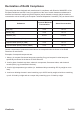
Declaration of RoHS Compliance This product has been designed and manufactured in compliance with Directive 2002/95/EC of the European Parliament and the Council on restriction of the use of certain hazardous substances in electrical and electronic equipment (RoHS Directive) and is deemed to comply with the maximum concentration values issued by the European Technical Adaptation Committee (TAC) as shown below: Proposed Maximum Concentration Actual Concentration Lead (Pb) 0.1% < 0.1% Mercury (Hg) 0.
Copyright Information Copyright © ViewSonic® Corporation, 2010. All rights reserved. Macintosh and Power Macintosh are registered trademarks of Apple Inc. Microsoft, Windows, Windows NT, and the Windows logo are registered trademarks of Microsoft Corporation in the United States and other countries. ViewSonic, the three birds logo, OnView, ViewMatch, and ViewMeter are registered trademarks of ViewSonic Corporation. VESA is a registered trademark of the Video Electronics Standards Association.
Projector Pro9500 User's Manual (detailed) Operating Guide About this manual Various symbols are used in this manual. The meanings of these symbols are described below. WARNING This symbol indicates information that, if ignored, could possibly result in personal injury or even death due to incorrect handling. CAUTION This symbol indicates information that, if ignored, could possibly result in personal injury or physical damage due to incorrect handling.
Contents Introduction...................................................................................... 6 Features............................................................................................................... 6 Checking the contents of package........................................................................ 6 Part names........................................................................................................... 7 Setting up...........................................
Contents AUDIO menu.................................................................................... 49 Volume, Speaker, Audio source, Hdmi audio, Mic level, Mic volume SCREEN menu................................................................................. 51 Language, Menu position, Blank, Start up, MyScreen, MyScreen Lock, Message, Source name, Template, C.c. OPTION menu.................................................................................
Contents Network Guide 1. Connection to the Network . ................................................. 108 1.1 System requirements .............................................................................. 108 1.1.1 Required equipment preparation ...................................................................................108 1.1.2 Hardware and software requirement for computer ....................................................... 108 1.2 Installing the “LiveViewer” ..........................
Contents 3. Web Control ........................................................................... 149 3.1 Logon ...................................................................................................... 3.2 Network Information ................................................................................ 3.3 Network Settings ..................................................................................... 3.4 Port Settings . ...............................................................
Introduction Introduction Features The projector provides you with the broad use by the following features. ü T his projector has a variety of I/O ports that supposedly cover for any business scene. The HDMI port can support various image equipment which have digital interface to get clearer pictures on a screen. ü This projector has a 1.7 times optical zoom, horizontal and vertical manual lens shift, allowing flexible installation.
Introduction Part names Projector (1) Lamp cover The lamp unit is inside. (2) Speakers (x2) (3) Filter cover The air filter and intake vent are inside. (4) Elevator feet (x2) (5) Elevator buttons (x2) (6) Remote sensor (7) Lens (8) Lens cover (9) Pocket caps (10) Intake vents (11) Control panel (12) Lens adjuster door The adjusters for the lens are behind the door. (13) AC IN (AC inlet) (14) Exhaust vent (15) Rear panel (16) Security bar (17) Battery cover The internal clock battery is inside.
Introduction Part names (continued) Control panel and Lens adjusters (1) Lens adjuster door (2) FOCUS ring (3) ZOOM ring (4) HORIZONTAL (horizontal) adjuster (5) VERTICAL (vertical) adjuster (6) LOCK (horizontal lens position lock) (7) STANDBY/ON button (8) INPUT button (9) MENU button (10) SECURITY indicator (11) LAMP indicator (12) TEMP indicator (13) POWER indicator (14) Cap storage pockets LOCK Rear panel (1) LAN port (2) USB TYPE A port (3) HDMI port (4) USB TYPE B port (5) MIC port (6) AUDIO IN1 po
Introduction Part names (continued) Remote control (1) VIDEO button (2) COMPUTER button (3) SEARCH button (4) STANDBY/ON button (5) ASPECT button (6) AUTO button (7) BLANK button (8) MAGNIFY - ON button (9) MAGNIFY - OFF button (10) MY SOURCE/DOC.
Setting up Setting up Install the projector according to the environment and manner the projector will be used in. For the case of installation in a special state such as ceiling mount, the specified mounting accessories and service may be required. Before installing the projector, consult your dealer about your installation. Arrangement Refer to the following tables T-1 to determine the screen size and projection distance. The values shown in the table are calculated for a full size screen.
Setting up Arrangement (continued) WARNING ►Install the projector where you can access the power outlet easily. If an abnormality should occur, unplug the projector urgently. Otherwise it could cause a fire or electric shock. ►Do not subject the projector to unstable conditions. If the projector falls or topples over, it could result in injury or damage to the projector and the surrounding things. Using a damaged projector could result in a fire and an electric shock.
Setting up Arrangement (continued) CAUTION ►Place the projector in a cool place with sufficient ventilation. The projector may shutdown automatically or may malfunction if its internal temperature is too high. Using a damaged projector could result in a fire and an electric shock. • Do not place the projector in direct sunlight or near hot objects such as heaters. • Keep a space of 30 cm or more between a side of the projector and other objects such as walls.
Setting up Connecting with your devices Before connecting the projector to a device, consult the manual of the device to confirm that the device is suitable for connecting with this projector and prepare the required accessories, such as a cable in accord with the signal of the device. Consult your dealer when the required accessory did not come with the product or the accessory is damaged.
Setting up Connecting with your devices (continued) Computer NOTE • Before connecting the projector to a computer, consult the computer’s manual and check the compatibility of the signal level, the synchronization methods and the display resolution output to the projector. - Some signal may need an adapter to input this projector. - Some computers have multiple screen display modes that may include some signals which are not supported by this projector.
Setting up Connecting with your devices (continued) Computer Access point USB storage device CAUTION ► Before connecting the projector to a network system be sure to obtain the consent of the administrator of the network. ►Do not connect the LAN port to any network that might have the excessive voltage. ►Before removing the USB storage device from the port of the projector, be sure to use the REMOVE USB function on the thumbnail screen to secure your data.
Setting up Connecting with your devices (continued) Digital video device VCR/DVD/Blu-ray Disc player NOTE • The HDMI port of this model is compatible with HDCP (High-bandwidth Digital Content Protection) and therefore capable of displaying a video signal from HDCP compatible DVD players or the like.
Setting up Connecting with your devices (continued) Monitor Speakers (with an amplifier) Microphone system Wired remote control (optional) NOTE • If a loud feedback noise is produced from the speaker, move the microphone away from the speaker. Microphone function • You can connect a dynamic microphone to the MIC port with a 3.5 mm mini-plug. In that case, the built-in speaker outputs the sound from the microphone, even while the sound from the projector is output.
Setting up Connecting to a power supply the connector of the power cord into the 1. Put AC IN (AC inlet) of the projector. plug the power cord’s plug into the 2. Firmly outlet. In a couple of seconds after the AC IN power supply connection, the POWER indicator will light up in steady orange. Please remember that when the DIRECT POWER ON function activated, the connection of the power supply make the projector turn on.
Remote control Remote control Installing the batteries Please insert the batteries into the remote control before using it. If the remote control starts to malfunction, try to replace the batteries. If you will not use the remote control for long period, remove the batteries from the remote control and store them in a safe place. Holding the hook part of the battery 1 2 3 cover, remove it. Align and insert the two AA batteries (HITACHI MAXELL, Part No.
Remote control Changing the frequency of remote control signal The accessory remote control has the two choices on signal frequency Mode 1:NORMAL and Mode 2:HIGH. If the remote control does not function properly, attempt to change the signal frequency. In order to set the Mode, please keep pressing the combination of two buttons listed below simultaneously for about 3 seconds. (2) (1) Set to Mode 1:NORMAL... VOLUME - and RESET buttons (2) Set to Mode 2:HIGH...
Power on/off Power on/off Turning on the power sure that the power cord is firmly and 1. Make correctly connected to the projector and the 2. STANDBY/ON button outlet. Make sure that the POWER indicator is steady orange. Then remove the lens cover. 3. POWER indicator Press STANDBY/ON button on the projector or the remote control. The projection lamp will light up and POWER indicator will begin blinking in green.
Operating Operating VOLUME +/- button Adjusting the volume VIDEO 1. MY SOURCE/ COMPUTER DOC.CAMERA Use the VOLUME +/VOLUME - buttons to adjust the volume. A dialog will appear on the screen to aid you in adjusting the volume. If you do not do anything, the dialog will automatically disappear after a few seconds. ● When is selected for current picture input port, the volume adjustment is disabled. Please see AUDIO SOURCE item of AUDIO menu.
Operating Selecting an input signal (continued) COMPUTER button on the remote control. 1. Press Each time you press the button, the projector switches its COMPUTER button input port from the current port as below. COMPUTER IN1 COMPUTER IN2 LAN USB TYPE B USB TYPE A VIDEO ASPECT MAGNIFY MY SOURCE/ COMPUTER DOC.CAMERA AUTO FREEZE ON ● While ON is selected for AUTO SEARCH item in OPTION menu, the projector will keep checking every port sequentially till an input signal is detected.
Operating Searching an input signal SEARCH button SEARCH button on the remote control. 1. Press The projector will start to check its input ports as below in VIDEO order to find any input signals. When an input is found, the projector will stop searching and display the image. If no signal is found, the projector will return to the state selected before the operation.
Operating Adjusting the projector’s elevator When the place to put the projector is slightly uneven to the left or right, use the elevator feet to place the projector horizontally. Using the feet can also tilt the projector in order to project at a suitable angle to the screen, elevating the front side of the projector within 12 degrees. This projector has 2 elevator feet and 2 elevator buttons. An elevator foot is adjustable while pushing the elevator button on the same side as it.
Operating Adjusting the lens 1. 2. Use the ZOOM ring to adjust the screen size. Use the FOCUS ring to focus the picture. 3. Turn the VERTICAL adjuster fully counter clockwise. Then turn it clockwise and adjust the vertical lens position upward. Turn the LOCK counter clockwise to loosen the lock of the HORIZONTAL adjuster. Turn the HORIZONTAL adjuster clockwise or counter clockwise to adjust the horizontal lens position. 4. 5. 6. 7.
Operating Using the automatic adjustment feature AUTO button on the remote control. 1. Press Pressing this button performs the following. AUTO button MY SOURCE/ COMPUTER DOC.CAMERA F or a computer signal The vertical position, the horizontal position and the horizontal phase will be automatically adjusted. Make sure that the application window is set to its maximum size prior to attempting to use this feature. A dark picture may still be incorrectly adjusted. Use a bright picture when adjusting.
Operating Correcting the distortion To correct the distortion of projected screen, you can select one of three options, AUTO, MANUAL and PERFECT FIT. AUTO: performs the automatic vertical keystone correction. MANUAL: allows you to adjust the vertical and horizontal keystone. PERFECT FIT: allows you to adjust each of the screen corners and sides to correct the distortion. 1. First press the KEYSTONE button to display the KEYSTONE menu, and point at one of items with the ▲/▼ buttons.
Operating PERFECT FIT When PERFECT FIT is pointed at, pressing the ► or ENTER button displays the KEYSTONE_PERFECT FIT dialog. If it is necessary to initialize the current adjustment, point at RESET in the dialog with the RESET button, and press the ENTER or INPUT button. Select one of the corners or sides to be adjusted with the ▲/▼/◄/► buttons and press the ENTER or INPUT button. Adjust the selected part as below. 2. 3. 4. 5.
Operating Using the magnify feature the MAGNIFY ON button on the remote control. 1. Press The picture will be magnified, and the MAGNIFY dialog will appear on the screen. When the MAGNIFY ON button is pressed for the first time after the projector is turned on, the picture will be zoomed by 1.5 times. On the dialog, triangle marks to show each direction will be displayed. MAGNIFY ON/OFF button VIDEO ASPECT MAGNIFY ON MY SOURCE/ COMPUTER DOC.
Operating Temporarily freezing the screen 1. Press the FREEZE button on the remote control. The “FREEZE” indication will appear on the screen (however, the indication will not appear when the OFF is selected for the MESSAGE item in the SCREEN menu), and the projector will go into the FREEZE mode, which the picture is frozen. To exit the FREEZE mode and restore the screen to normal, press the FREEZE button again. FREEZE button VIDEO MY SOURCE/ COMPUTER DOC.
Operating Using the menu function This projector has the following menus: PICTURE, IMAGE, INPUT, SETUP, AUDIO, SCREEN, OPTION, NETWORK, SECURITY and EASY MENU. EASY MENU consists of functions often used, and the other menus are classified into each purpose and brought together as the ADVANCED MENU. Each of these menus is operated using the same methods. While the projector is displaying any menu, the MENU button on the projector works as the cursor buttons.
Operating Using the menu function (continued) close the MENU, press the MENU button again or select EXIT and press 3. To the ◄ cursor button or ENTER button. Even if you do not do anything, the dialog will automatically disappear after about 30 seconds. ● I f you want to move the menu position, use the cursor buttons after pressing the POSITION button. ● Some functions cannot be performed when a certain input port is selected, or when a certain input signal is displayed.
EASY MENU EASY MENU From the EASY MENU, items shown in the table below can be performed. Select an item using the ▲/▼ cursor buttons. Then perform it according to the following table. Item ASPECT AUTO KEYSTONE Description Using the ◄/► buttons switches the mode for aspect ratio. See the ASPECT item in IMAGE menu. Using the ► button executes the auto keystone function. See the AUTO KEYSTONE item in SETUP menu. KEYSTONE Using the ◄/► buttons corrects the vertical keystone distortion.
EASY MENU Item ECO MODE MIRROR Description Using the ◄/► buttons turns off/on the Eco mode. See the ECO MODE item in SETUP menu. Using the ◄/► buttons switches the mode for mirror status. See the MIRROR item in SETUP menu. RESET Performing this item resets all of the EASY MENU items except the FILTER TIME and LANGUAGE. A dialog is displayed for confirmation. Selecting the OK using the ► button performs resetting. FILTER TIME The usage time of the air filter is shown in the menu.
PICTURE menu PICTURE menu From the PICTURE menu, items shown in the table below can be performed. Select an item using the ▲/▼ cursor buttons, and press the ► cursor button or ENTER button to execute the item. Then perform it according to the following table. Item BRIGHTNESS CONTRAST Description Using the ◄/► buttons adjusts the brightness. Dark ó Light Using the ◄/► buttons adjusts the contrast. Weak ó Strong Using the ▲/▼ buttons switches the gamma mode.
PICTURE menu Item Description Using the ▲/▼ buttons switches the color temperature mode. 2 MID 2 CUSTOM 1 HIGH 1 CUSTOM 3 LOW 6 Hi-BRIGHT-3 3 CUSTOM 6 CUSTOM 5 CUSTOM 5 Hi-BRIGHT-2 4 CUSTOM 4 Hi-BRIGHT-1 To adjust CUSTOM COLOR TEMP Selecting a mode whose name includes CUSTOM and then pressing the ► button or the ENTER button displays a dialog to aid you in adjusting the OFFSET and GAIN of the selected mode.
PICTURE menu Item SHARPNESS Description Using the ◄/► buttons adjusts the sharpness. Weak ó Strong • There may be some noise and/or the screen may flicker for a moment when an adjustment is made. This is not a malfunction. Using the ▲/▼ cursor buttons changes the active iris control mode. PRESENTATION ó THEATER ó OFF ACTIVE IRIS MY MEMORY ViewSonic PRESENTATION : The active iris displays the best presentation image for both bright and dark scenes.
IMAGE menu IMAGE menu From the IMAGE menu, items shown in the table below can be performed. Select an item using the ▲/▼ cursor buttons, and press the ► cursor button or ENTER button to execute the item. Then perform it according to the following table. Item Description Using the ▲/▼ buttons switches the mode for aspect ratio.
IMAGE menu Item Description V POSITION Using the ◄/► buttons adjusts the vertical position. Down ó Up • Over-adjusting the vertical position may cause noise to appear on the screen. If this occurs, please reset the vertical position to the default setting. Pressing the RESET button when the V POSITION is selected will reset the V POSITION to the default setting. • When this function is performed on a video signal or an s-video signal, the range of this adjustment depends on OVER SCAN setting.
IMAGE menu Item Description H PHASE Using the ◄/► buttons adjusts the horizontal phase to eliminate flicker. Right ó Left • This item can be selected only for a computer signal or a component video signal. This function is unavailable for a signal from the LAN, USB TYPE A, USB TYPE B or HDMI port. H SIZE Using the ◄/► buttons adjusts the horizontal size. Small ó Large • This item can be selected only for a computer signal.
INPUT menu INPUT menu From the INPUT menu, items shown in the table below can be performed. Select an item using the ▲/▼ cursor buttons, and press the ► cursor button or ENTER button to execute the item. Then perform it according to the following table. Item Description Using the ▲/▼ buttons switches the progress mode.
INPUT menu Item Description VIDEO FORMAT The video format for S-VIDEO port and VIDEO port can be set. (1) Use the ▲/▼ buttons to select the input port. (2) Using the ◄/► buttons switches the mode for video format. AUTO ó NTSC ó PAL ó SECAM N-PAL ó M-PAL ó NTSC4.43 • This item is performed only for a video signal from the VIDEO port or the S-VIDEO port. • The AUTO mode automatically selects the optimum mode. • The AUTO operation may not work well for some signals. If the picture becomes unstable (e.g.
INPUT menu Item Description COMPUTER IN The computer input signal type for COMPUTER IN1 and IN2 ports can be set. (1) Use the ▲/▼ buttons to select the COMPUTER IN port to be set. (2) Use the ◄/► buttons to select the computer input signal type. AUTO ó SYNC ON G OFF • Selecting the AUTO mode allows you to input a sync on G signal or component video signal from the port. • In the AUTO mode, the picture may be distorted with certain input signals.
INPUT menu Item Description RESOLUTION The resolution for the COMPUTER IN1 and COMPUTER IN2 input signals can be set on this projector. (1) In the INPUT menu select the RESOLUTION using the ▲/▼ buttons and press the ► button. The RESOLUTION menu will be displayed. (2) In the RESOLUTION menu select the resolution you wish to display using the ▲/▼ buttons. Selecting AUTO will set a resolution appropriate to the input signal.
SETUP menu SETUP menu From the SETUP menu, items shown in the table below can be performed. Select an item using the ▲/▼ cursor buttons, and press the ► cursor button or ENTER button to execute the item. Then perform it according to the following table. Item Description Selecting this item performs the Automatic keystone distortion correction. Projector automatically corrects vertical keystone distortion due to the (forward/backward) setup angle by itself.
SETUP menu Item KEYSTONE PERFECT FIT Description Using the ◄/► buttons corrects the horizontal keystone distortion. Shrink the right of the image ó Shrink the left of the image • The adjustable range of this function will vary among inputs. For some input, this function may not work well. • When the horizontal lens shift is not set to the center, this function may not work well. • This function is unavailable when the TRANSITION DETECTOR is ON or the screen is adjusted by PERFECT FIT.
SETUP menu Item Description STANDBY MODE Using ▲/▼ buttons switches the standby mode setting between NORMAL and SAVING. NORMAL ó SAVING When SAVING is selected, the power consumption in the standby mode is lowered with some functional restriction as below: • When SAVING is selected, the RS-232C communication control except to turn the projector on and the network function are disabled while the projector is in the standby mode.
AUDIO menu AUDIO menu From the AUDIO menu, items shown in the table below can be performed. Select an item using the ▲/▼ cursor buttons, and press the ► cursor button or the ENTER button to execute the item. Then perform it according to the following table. Item Description VOLUME Using the ◄/► buttons adjusts the volume. Low ó High SPEAKER Using the ▲/▼ buttons turns on/off the built-in speaker. ON ó OFF When OFF is selected, the built-in speaker does not work.
AUDIO menu Item Description HDMI AUDIO Using the ▲/▼ buttons switches the mode for the HDMITM audio. Check each of the two modes provided and select the suitable one for your HDMITM audio device. 1ó2 MIC LEVEL Using the ▲/▼ buttons switches the input level to match that of the microphone connected to the MIC port. HIGH ó LOW HIGH: for a microphone with an amplifier. LOW: for a microphone without an amplifier.
SCREEN menu SCREEN menu From the SCREEN menu, items shown in the table below can be performed. Select an item using the ▲/▼ cursor buttons, and press the ► cursor button or ENTER button to execute the item. Then perform it according to the following table. Item LANGUAGE Description Using the ▲/▼/◄/► buttons switches the OSD (On Screen Display) language. ENGLISH ó FRANÇAIS ó DEUTSCH ó ESPAÑOL (shown in the LANGUAGE dialog) Press the ENTER or INPUT button to save the language setting.
SCREEN menu Item Description MyScreen This item allows you to capture an image for use as a MyScreen image which can be used as the BLANK screen and START UP screen. Display the image you want to capture before executing the following procedure. 1. Selecting this item displays a dialog titled “MyScreen”. It will ask you if you start capturing an image from the current screen. Please wait for the target image to be displayed, and press the ENTER or INPUT button when the image is displayed.
SCREEN menu Item Description MyScreen Lock Using the ▲/▼ buttons turns on/off the MyScreen lock function. ON ó OFF When the ON is selected, the item MyScreen is locked. Use this function for protecting the current MyScreen. • This function cannot be selected when the ON is selected to the MyScreen PASSWORD item in SECURITY menu. MESSAGE Using the ▲/▼ buttons turns on/off the message function. ON ó OFF When the ON is selected, the following message function works.
SCREEN menu Item Description Each input port for this projector can have a name applied to it. (1) Use the ▲/▼ buttons on the SCREEN menu to select SOURCE NAME and press the ► or ENTER button. The SOURCE NAME menu will be displayed. (2) Use the ▲/▼ buttons on the SOURCE NAME menu to select the port to be named and press the ► button. The SOURCE NAME dialog will be displayed. Right side of the menu is blank until a name is specified.
SCREEN menu Item Description SOURCE NAME (Continued) (6) The current name will be displayed on the first line. Use the ▲/▼/◄/► buttons and the ENTER or INPUT button to select and enter characters. To erase 1 character at one time, press the RESET button or press the ◄ and INPUT button at the same time. Also if you move the cursor to DELETE or ALL CLEAR on screen and press the ENTER or INPUT button, 1 character or all characters will be erased. The name can be a maximum of 16 characters.
SCREEN menu Item Description The C.C. is the function that displays a transcript or dialog of the audio portion of a video, files or other presentation or other relevant sounds. It is required to have NTSC format video or 480i@60 format component video source supporting C.C. feature to utilize this function. It may not work properly, depending on equipment or signal source. In this case, please turn off the Closed Caption.
OPTION menu OPTION menu From the OPTION menu, items shown in the table below can be performed. Select an item using the ▲/▼ cursor buttons, and press the ► cursor button or ENTER button to execute the item, except for the items LAMP TIME and FILTER TIME. Then perform it according to the following table. Item Description AUTO SEARCH Using the ▲/▼ buttons turns on/off the automatic signal search function.
OPTION menu Item Description Using the ▲/▼ buttons adjusts the time to count down to automatically turn the projector off. Long (max. 99 minutes) ó Short (min. 0 minute = DISABLE) AUTO POWER OFF USB TYPE B When the time is set to 0, the projector is not turned off automatically. When the time is set to 1 to 99, and when the passed time with no-signal or an unsuitable signal reaches at the set time, the projector lamp will be turned off.
OPTION menu Item Description LAMP TIME The lamp time is the usage time of the lamp, counted after the last resetting. It is shown in the OPTION menu. Pressing the RESET button on the remote control or the ► button of the projector displays a dialog. To reset the lamp time, select the OK using the ► button. CANCEL OK • Please reset the lamp time only when you have replaced the lamp, for a suitable indication about the lamp.
OPTION menu Item Description MY BUTTON This item is to assign one of the following functions to MY BUTTON 1/2 on the remote control. (1) Use the ▲/▼ buttons on the MY BUTTON menu to select a MY BUTTON - (1/2) and press the ► or ENTER button to display the MY BUTTON setup dialog. (2) Then using the ▲/▼/◄/► buttons sets one of the following functions to the chosen button. Press the ENTER or INPUT button to save the setting. • LAN: Selects input from LAN port.
OPTION menu Item Description MY BUTTON (Continued) • ACTIVE IRIS: Changes the active iris mode. • PICTURE MODE: Changes the PICTURE MODE. • FILTER RESET: Displays the filter time reset confirmation dialogue. • TEMPLATE: Makes the template pattern selected to the TEMPLATE item appear or disappear. • AV MUTE: Turns the picture and audio on/off. • RESOLUTION: Turns on/off the RESOLUTION dialog. • MIC VOLUME: Turns on/off the MIC VOLUME dialog. • ECO MODE: Turns on/off the ECO MODE dialog.
OPTION menu Item Description Selecting this item displays the SERVICE menu. Select an item using the ▲/▼ buttons, and press the ► button or the ENTER button on the remote control to execute the item. FAN SPEED Using the ▲/▼ buttons switches the rotation speed of the cooling fans. The HIGH is the mode for use at highlands etc. If the projector is used at an altitude of about 1200 m or higher, select HIGH. Otherwise, select NORMAL. Note that the projector is noisier when the HIGH is selected.
OPTION menu Item Description KEY LOCK (1) Use the ▲/▼ buttons to choose the operations control. CONTROL PANEL ó REMOTE CONTROL (2) Use the ◄/► buttons to select ON or OFF. ON ó OFF Selecting ON in Step 2 locks the buttons except STANDBY/ON on the operations control selected in Step 1. Selecting OFF releases the locked buttons on the operations control selected in Step 1. • Please use this function to prevent tampering or accidental operation. SERVICE (continued) REMOTE FREQ.
OPTION menu Item Description COMMUNICATION TYPE Select the communication type for transmission via the CONTROL port. NETWORK BRIDGE ó OFF NETWORK BRIDGE: Select this type, if it is required to control an external device as a network terminal, via this projector from the computer. The CONTROL port doesn't accept RS-232C commands (6. Network Bridge Function in the Network Guide) OFF: Select this mode to receive RS-232C commands using the CONTROL port. • OFF is selected as the default setting.
OPTION menu Item Description RESPONSE LIMIT TIME Select the time period to wait for receiving response data from other device communicating by the NETWORK BRIDGE and the HALF-DUPLEX through the CONTROL port. OFF ó 1s ó 2s ó 3s SERVICE (continued) OFF: Select this mode if it is not required to check the responses from the device that the projector sends data to. In this mode, the projector can send out data from the computer continuously.
OPTION menu Item Description INFORMATION Selecting this item displays a dialog titled “INPUT_INFORMATION”. It shows the information about the current input. SERVICE (continued) • The “FRAME LOCK” message on the dialog means the frame lock function is working. • The “SCART RGB” message means the COMPONENT ports is working as a SCART RGB input port. Please refer to the COMPONENT item in INPUT menu. • This item can't be selected for no signal and sync out.
NETWORK menu NETWORK menu Remember that incorrect network settings on this projector may cause trouble on the network. Be sure to consult with your network administrator before connecting to an existing access point on your network. Select “NETWORK” from the main menu to access the following functions. Select an item using the ▲/▼ cursor buttons on the projector or remote control, and press the ► cursor button on the projector or remote control, or ENTER button on the remote control to execute the item.
NETWORK menu Item SETUP (continued) Description IP ADDRESS Use the ▲/▼/◄/► buttons to enter the IP ADDRESS. This function can only be used when DHCP is set to OFF. • The IP ADDRESS is the number that identifies this projector on the network. You cannot have two devices with the same IP ADDRESS on the same network. • The IP ADDRESS “0.0.0.0” is prohibited. SUBNET MASK Use the ▲/▼/◄/► buttons to enter the same SUBNET MASK used by your computer. This function can only be used when DHCP is set to OFF.
NETWORK menu Item Description PROJECTOR NAME (1) Use the ▲/▼ buttons on the NETWORK menu to select the PROJECTOR NAME and press the ► button. The PROJECTOR NAME dialog will be displayed. (2) The current PROJECTOR NAME will be displayed on the first 3 lines. Particular projector name is pre-assigned by default. Use the ▲/▼/◄/► buttons and the ENTER or INPUT button to select and enter characters. To erase 1 character at one time, press the RESET button or press the ◄ and INPUT button at the same time.
NETWORK menu Item Description Selecting this item displays the MY IMAGE menu. To store images in the projector, the application software PJImg/Projector Image Tool that can be downloaded from our website is required. Use the ▲/▼ buttons to select an item which is a still image by the MY IMAGE (4. My Image Function in the Network Guide) and the ► or ENTER button to display the image. • The item without image stored cannot be selected. • The image names are each displayed in 16 characters or less.
NETWORK menu Item Description Selecting this item displays the PRESENTATION menu. Use ▲/▼ buttons to select one of the following items, then press ► or ENTER button to use the function. If you set a computer to the Presenter mode while its image is projected, the projector is occupied by the computer and access from any other computer is blocked. Use this function to quit the Presenter mode and allow other computers to access the projector. QUIT PRESENTER Select this item to display a dialog.
NETWORK menu Item Description MULTI PC MODE (continued) PRESENTATION (continued) • To change from Multi PC mode to Single PC mode, select one of computers in the dialog using the ▲/▼/◄/► buttons and press the ENTER or INPUT button. Press the ► button to choose OK, and then press ENTER or INPUT again. The image for the selected computer is displayed on full screen. • To change from Single PC mode to Multi PC mode, press ► button to choose OK in the dialog and press the ENTER or INPUT button.
NETWORK menu Item Description Selecting this item displays the NETWORK_INFORMATION dialog for confirming the network settings. INFORMATION • For the details of PASSCODE, see the section 1.5 Selecting the network connection method in the Network Guide. • Only the first 16 characters of the projector name are displayed. • When the voltage level of the battery for the built in clock decreases, the set time may become incorrect even though accurate date and time are input. Replace the battery suitably (93).
SECURITY menu SECURITY menu This projector is equipped with security functions. From the SECURITY menu, items shown in the table below can be performed. To use SECURITY menu: User registration is required before using the security functions. Enter to the SECURITY menu 1. Press the ► button. The ENTER PASSWORD box will be displayed. 2. Use the ▲/▼/◄/► buttons to enter the registered password. The factory default password is as follows. Pro9500: 4501 This password can be changed.
SECURITY menu Item Description The MyScreen PASSWORD function can be used to prohibit access to the MyScreen function and prevent the currently registered MyScreen image from being overwritten. 1 Turning on the MyScreen PASSWORD MyScreen PASSWORD 1-1 Use the ▲/▼ buttons on the SECURITY menu to select MyScreen PASSWORD and press the ► button to display the MyScreen PASSWORD on/ off menu. 1-2 Use the ▲/▼ buttons on the MyScreen PASSWORD on/off menu to select ON.
SECURITY menu Item Description PIN LOCK is a function which prevents the projector from being used unless a registered Code is input. 1 Turning on the PIN LOCK PIN LOCK 1-1 Use the ▲/▼ buttons on the SECURITY menu to select PIN LOCK and press the ► button or the ENTER button to display the PIN LOCK on/off menu. 1-2 Use the ▲/▼ buttons on the PIN LOCK on/ off menu to select ON and the Enter PIN Code box will be displayed. 1-3 Input a 4 part PIN code using the ▲/▼/◄/►, COMPUTER or INPUT button.
SECURITY menu Item Description If this function is set to ON when the vertical angle of the projector or MIRROR setting at which the projector is turned on is different than the previously recorded, the TRANSITION DETECTOR ON alarm will be displayed and the projector will not display the input signal. • To display the signal again, set this function OFF. • After about 5 minutes of displaying the TRANSITION DETECTOR ON alarm, the lamp will turn off.
SECURITY menu Item Description The MY TEXT PASSWORD function can prevent the MY TEXT from being overwritten. When the password is set for the MY TEXT; • The MY TEXT DISPLAY menu will be unavailable, which can prohibit changing the DISPLAY setting. • The MY TEXT WRITING menu will be unavailable, which can prevent the MY TEXT from being overwritten.
SECURITY menu Item Description MY TEXT DISPLAY (1) Use the ▲/▼ buttons on the SECURITY menu to select the MY TEXT DISPLAY and press the ► or ENTER button to display the MY TEXT DISPLAY on/off menu. (2) Use the ▲/▼ buttons on the MY TEXT DISPLAY on/off menu to select on or off. ON ó OFF When it is set ON, the MY TEXT will be displayed on the START UP screen and the INPUT_ INFORMATION when the INFORMATION on the SERVICE menu is chosen.
Presentation tools The projector has the following two convenient tools that enable on-screen presentations easily and quickly: - PC-LESS Presentation - USB Display PC-LESS Presentation The PC-LESS Presentation reads image data from storage media inserted into the USB TYPE A port and displays the image on the following modes. The PC-LESS Presentation can be started by selecting the USB TYPE A port as the input source. This feature allows you to make your presentations without using your computer.
PC-LESS Presentation (continued) Thumbnail mode The Thumbnail mode displays the images stored in a USB storage device on the Thumbnail screen. Maximum 20 images are displayed in a screen. If you wish, you can jump into the Full Screen mode or Slideshow mode, after you select some images in the Thumbnail mode. The Thumbnail mode will be started as the primary function of the PC-LESS Presentation after selecting the USB TYPE A port as the input source.
PC-LESS Presentation (continued) Operating by buttons or keys You can control the images in the Thumbnail screen with the remote control or keypad or a web browser software. The following functions can be supported while the Thumbnail is displayed. Button operation Functions The remote control The keypad on the projector Web Remote in web browser software.
PC-LESS Presentation (continued) Operating by the menu on the Thumbnail screen You can also control the images by using the menu on the Thumbnail screen. Item Functions Moves to an upper folder. SORT Allows you to sort files and folders as following. RETURN Press the ► cursor button or ENTER to return to the Thumbnail screen. NAME UP Sorts in ascending order by file name. NAME DOWN Sorts in descending order by file name. DATE UP Sorts in ascending order by file date.
Presentation tools PC-LESS Presentation (continued) NOTE • These operations are not accessible while the projector OSD is displayed. • The Thumbnail mode shows 20 pictures in 1 page as maximum. • It is not possible to change the input port by using the INPUT button when the Thumbnail screen, Slideshow, or Full Screen is displayed. • Some error icons will be displayed in the Thumbnail. This file seems to be broken or not supported format.
Presentation tools PC-LESS Presentation (continued) Full Screen Mode The Full Screen mode shows a full display image. To display in Full Screen mode, select an image in the Thumbnail screen. Then press the ENTER button on the remote control or the INPUT button on the keypad, or click [ENTER] on the Web Remote Control. Full screen display The following functions can be supported in the Full Screen mode. Button operation The remote control The keypad on the projector Web Remote in web browser software.
Presentation tools PC-LESS Presentation (continued) Slideshow mode The Slideshow mode displays images in full screen and switches the images at intervals set in INTERVAL on the Thumbnail screen menu. You can start this function from the Slideshow menu. To display the Slideshow menu, select the SLIDESHOW button in the Thumbnail mode and press the ENTER button on the remote control or INPUT button on the projector. The following operations can be accessible while the Slideshow is displayed.
Presentation tools PC-LESS Presentation (continued) You can play the Slideshow at your desired configuration. Configure the Slideshow items in the Thumbnail. : Returns to the thumbnail mode. 1) RETURN 2) PLAY :P lay the Slideshow. 3) START : Set the beginning number of the Slideshow. 4) STOP : Set the end number of the Slideshow. 5) INTERVAL : Set the interval time of the Slideshow.
Presentation tools PC-LESS Presentation (continued) Playlist The Playlist is a DOS format text file, which decides the order of displayed still image files in the Thumbnail or Slideshow. The playlist file name is “playlist.txt” and it can be edited on a computer. It is created in the folder that contains the selected image files when the PC-LESS Presentation is started or the Slideshow is configured. [Example of “playlist.
Presentation tools USB Display The projector can display images transferred from a computer via an USB cable. Hardware and software requirement for computer • OS: One of the following. (32 bit version only) Windows ® XP Home Edition /Professional Edition Windows Vista ® Home Basic /Home Premium /Business /Ultimate /Enterprise Windows ® 7 Starter /Home Basic /Home Premium /Professional / Ultimate /Enterprise • CPU: Pentium 4 (2.
Presentation tools USB Display (continued) Right-Click menu The menu shown in the right will be displayed when you right-click the application icon in the Windows notification area. Display : The Floating menu is displayed, and the icon disappears from the Windows notification area. Quit : The application is closed, and the icon disappears from the Windows notification area. NOTE • If you wish to restart the application, you need to unplug the USB cable and plug it again.
Presentation tools USB Display (continued) Options window If you select the Option button on the Floating menu, the Options window is displayed. Optimize Performance The “LiveViewer Lite for USB” captures screenshots in JPEG data and sends them to the projector. The “LiveViewer Lite for USB” has two options that have different compression rate of JPEG data. Transmission speed Speed takes priority over Image quality. It makes JPEG compression rate higher.
Maintenance Maintenance Replacing the lamp A lamp has finite product life. Using the lamp for long periods of time could cause the pictures darker or the color tone poor. Note that each lamp has a different lifetime, and some may burst or burn out soon after you start using them. Preparation of a new lamp and early replacement are recommended. To prepare a new lamp, make contact with your dealer and tell the lamp type number.
Maintenance Replacing the lamp (continued) Lamp warning HIGH VOLTAGE HIGH TEMPERATURE HIGH PRESSURE WARNING ►The projector uses a high-pressure mercury glass lamp. The lamp can break with a loud bang, or burn out, if jolted or scratched, handled while hot, or worn over time. Note that each lamp has a different lifetime, and some may burst or burn out soon after you start using them.
Maintenance Cleaning and replacing the air filter Please check and clean the air filter periodically. When the indicators or a message prompts you to clean the air filter, comply with it as soon as possible. The air filter of this projector consists of a filter cover and a filter unit with two types of filter. If one or both of the filters are damaged or heavily soiled, replace the filter unit with a new one. The specified filter unit also comes with a replacement lamp for this projector.
Maintenance Cleaning and replacing the air filter (continued) Put the filter cover back into the place. 10. the projector on and reset the filter time using the FILTER TIME item in 11.Turn the EASY MENU. (1) Press the MENU button to display a menu. (2) Point at the FILTER TIME using the ▲/▼ cursor buttons, then press the ► cursor (or the ENTER / the RESET) button. A dialog will appear. (3) Press the ► cursor button to select the “OK” on the dialog. It performs resetting the filter time.
Maintenance Replacing the internal clock battery OP CLO EN SE This projector has internal clock that uses a battery. When the clock of the network function does not work correctly, please try solution by replacement of the battery: HITACHI MAXELL, part number CR2032 or CR2032H. Turn the projector off, and unplug the power cord. Allow the projector to cool sufficiently. After making sure that the projector has cooled Raised dot Knob adequately, slowly turn over the projector, so that the bottom is facing.
Maintenance Other care Inside of the projector In order to ensure the safe use of your projector, please have it cleaned and inspected by your dealer about once every year. Caring for the lens If the lens is flawed, soiled or fogged, it could cause deterioration of display quality. Please take care of the lens, being cautious of handling. the projector off, and unplug the power cord. Allow the projector to cool 1. Turn sufficiently.
Troubleshooting Troubleshooting If an abnormal operation should occur, stop using the projector immediately. WARNING ►Never use the projector if abnormal operations such as smoke, Troubleshooting strange odor, excessive sound, damaged casing or elements or cables, penetration of liquids or foreign matter, etc. should occur. In such cases, immediately disconnect the power plug from the power outlet. After making sure that the smoke or odor has stopped, contact to your dealer or service company.
Troubleshooting Related messages (continued) Message Description The internal temperature is rising. Please turn the power off, and allow the projector to cool down at least 20 minutes. After having confirmed the following items, please turn the power ON again. • Is there blockage of the air passage aperture? • Is the air filter dirty? • Does the peripheral temperature exceed 35°C? • Is the setting for FAN SPEED appropriate? For details on FAN SPEED, refer to FAN SPEED of SERVICE in the OPTION menu.
Troubleshooting Regarding the indicator lamps When operation of the LAMP, TEMP and POWER indicators differs from usual, check and cope with it according to the following table. For the SECURITY indicator, see SECURITY INDICATOR in the SECURITY menu. POWER LAMP TEMP Description indicator indicator indicator Lighting Turned Turned The projector is in a standby state. In Orange off off Please refer to the section “Power on/off”. Blinking In Green Turned off Turned off The projector is warming up.
Troubleshooting Regarding the indicator lamps (continued) POWER LAMP TEMP indicator indicator indicator Description There is a possibility that the interior portion has become heated. Blinking In Red or Lighting In Red Turned off Lighting In Red Please turn the power off, and allow the projector to cool down at least 20 minutes. After the projector has sufficiently cooled down, please make confirmation of the following items, and then turn the power on again.
Troubleshooting Phenomena that may be easy to be mistaken for machine defects About the phenomenon confused with a machine defect, check and cope with it according to the following table. Phenomenon Cases not involving a machine defect The electrical power cord is not plugged in. Correctly connect the power cord. The main power source has been interrupted during operation such as by a power outage (blackout), etc.
Troubleshooting Phenomena that may be easy to be mistaken for machine defects (continued) Cases not involving a machine defect Reference page The signal cables are not correctly connected. Correctly connect the audio cables. 10 ~ 14 Phenomenon Sound does not come out. The MUTE function is working. Restore the sound pressing MUTE or VOLUME +/- button on the remote control. 19 The volume is adjusted to an extremely low level.
Troubleshooting Phenomena that may be easy to be mistaken for machine defects (continued) Phenomenon Video screen display freezes. Colors have a faded- out appearance, or Color tone is poor. Pictures appear dark. Pictures appear blurry. Some kind of image degradation such as flickering or stripes appear on screen. Cases not involving a machine defect The FREEZE function is working. Press FREEZE button to restore the screen to normal. Color settings are not correctly adjusted.
Troubleshooting Phenomena that may be easy to be mistaken for machine defects (continued) Phenomenon Cases not involving a machine defect Reference page The computer cannot start up in the current hardware configuration. Disconnect the USB cable from the computer, then reconnect it after starting up the computer. 12 The SAVING function is working. Select NORMAL for STANDBY MODE item in the SETUP menu. 45 RS-232C does not work. The COMMUNICATION TYPE for the CONTROL port is set to NETWORK BRIDGE.
Specifications Specifications Item Product name Liquid Crystal Panel Lamp Speaker Power supply/ Rated current Power consumption Temperature range Size Weight (mass) Ports Optional parts ViewSonic Liquid crystal projector Specification 786,432 pixels (1024 horizontal x 768 vertical) 245 W UHP 16 W mono (8 W x2) AC100-120 V: 4.0 A, AC220-240 V: 2.0 A AC100-120 V: 380 W, AC220-240 V: 360 W 5 ~ 35 °C (Operating) 401 (W) x 103 (H) x 318 (D) mm * Not including protruding parts. approx. 4.
[unit: mm] ViewSonic 107 Pro9500
1. Connection to the network Network Guide 1. Connection to the network 1.1 System requirements 1.1.1 Required equipment preparation The following equipments are required to connect the projector to your computer through the network. üP rojector üL AN cable (to connect the projector to a network): CAT-5 or greater üC omputer (minimum 1 set): equipped with the network feature (100Base-TX or 10Base-T) 1.1.
1. Connection to the network 1.1 System requirements (continued) NOTE • Referring to the manual of your computer or Windows, select the following or a smaller display resolution for the computer. 1024 x 768 (XGA) When a resolution larger than the specified resolution is selected, the projector will convert and display in the specified resolution, and the display speed may become faster.
1. Connection to the network 1.2 Installing the “LiveViewer” 1.2.1 Installing the “LiveViewer” The “LiveViewer” software needs to be installed on all the computers to connect to the projector through a network. You need to log in as an administrator user to install the software. 1) Turn on the computer. 2) Shut down all applications. 3) Insert the accompanying CD-ROM into the computer's CD-ROM drive. 4) Click on the [Start] button on the toolbar and select the “Run”.
1. Connection to the network 1.2 Installing the “LiveViewer” (continued) 8) The License Agreement dialog appears. If you accept it, select “I accept the terms of the license agreement” and press the [Next]. 9) The Choose Destination Location dialog appears. Press the [Next]. NOTE • The C:\Program Files\Projector Tools\LiveViewer folder will be created and the program will be installed into that folder. If you wish to install to a different folder, click the [Browse] and select another folder.
1. Connection to the network 1.3 Process to connect the network Before connecting your computer and projector via a network, make sure that the LAN port is selected as the input source on the projector. (Operating in the Operating Guide) Otherwise a connection cannot be established. 1.3.1 Process overview An overview of the process to connect your computer and the projector via a network is shown below.
1. Connection to the network 1.3 Process to connect the network (continued) 1.3.2 Starting the “LiveViewer” Start the “LiveViewer” in your computer, taking one of the followings. ● Double click the “LiveViewer” icon on the Desktop in your computer ● Select “Start” → “All Programs” → “Projector Tools” → “LiveViewer” on Windows menu. Then, proceed to item 1.4 Selecting the network connection mode.
1. Connection to the network 1.4 Selecting the network connection mode After starting the “LiveViewer”, the “Select the Network Connection” screen comes up. Select the network connection that you would like to use. There are 3 options in the menu. • Wireless LAN • Wired LAN • My Connection If you select either the wireless LAN or wired LAN, proceed to item 1.4.1 Selecting either the wireless LAN or wired LAN. If you select My Connection, jump to item 1.4.2 Selecting My Connection.
1. Connection to the network 1.4 Selecting the network connection mode (continued) n A network connection was not established. The screen is displayed in the case that the projector is not connected with a LAN cable to your computer when the wired LAN is selected. Be sure that the projector is connected with a LAN cable to your computer. Click the [OK], then the screen is back to the previous one to select the network connection mode.
1. Connection to the network 1.4 Selecting the network connection mode (continued) 1.4.2 Selecting My Connection Select the [My Connection] and click the [Connect]. If you select the My Connection, the computer is connected to the projector through the network by using the profile data that is preassigned to My Connection. When you select the My Connection, the computer immediately starts the connection to the projector. Proceed to item 1.8 Confirming the connection to your destination.
1. Connection to the network 1.4 Selecting the network connection mode (continued) n Are you sure you want to connect the selected projector? The message is appeared when the wireless adapter you selected is already used for another network connection. • To connect, click the [Yes]. Proceed to item 1.8 Confirming the connection to your destination. • Not to connect, click the [No] to return to the screen to select the network connection mode.
1. Connection to the network 1.5 Selecting the network connection method There are some options to connect to the network. • Enter PassCode • Configure Manually • Select From List Select one of them to meet your requirement. Enter PassCode If you want to use the Passcode for network connection, select the [Enter PassCode] and click the [Next]. The Passcode is given by the projector on screen. And you simply input the Passcode to the “LiveViewer” to connect the network. Proceed to item 1.5.
1. Connection to the network 1.5 Selecting the network connection method (continued) 1.5.1 Passcode connection The unique Passcode system brings you very quick and simple connection to the network. The Passcode is a code that expresses the network setting in the projector. If you input the code in the “LiveViewer” in your computer, the network setting in the projector and computer can be matched and the connection will be established immediately. The section is intended to explain how to use the Passcode.
1. Connection to the network 1.5 Selecting the network connection method (continued) Method 2 1) Turn on the projector, and make sure that the projector image is on screen. 2) Press the MENU button on the remote control or the ▲/▼ buttons on the projector to show the menu on screen. 3) Use the ▲/▼ cursor buttons to select the “ADVANCED MENU”, and use the ► cursor button to enter the item. 4) Use the ▲/▼ cursor buttons to select the NETWORK, and use the ► cursor button to enter the item.
1. Connection to the network 1.5 Selecting the network connection method (continued) (2) Entering the Passcode If you select [Enter PassCode] at item 1.5, the “Please enter the PassCode” screen is displayed. Please enter the Passcode divided 4-digit each in 3 boxes (total 12-digit). Example PASSCODE: 1234 - 5678 - 9ABC After entering the Passcode, click the [Connect] to start the connection to the projector. Proceed to item 1.8 Confirming the connection to your destination.
1. Connection to the network 1.5 Selecting the network connection method (continued) n A network connection could not be established. Windows prevented network configuration changes. You may log in the Windows under User authority. Click the [OK], then the “LiveViewer” main menu is displayed even though the network is not established. Click on the main and go back to item 1.5 Selecting the network connection method. Consult to the network administrator. Log in the Windows under Administrator authority.
1. Connection to the network 1.5 Selecting the network connection method (continued) If you put a check mark in the box “Not displaying confirmation dialog for adding Network settings”, the projector memorizes current configuration and this dialog is not displayed again. To display this dialog again, click Option icon in the “LiveViewer” main menu and remove the check mark in the box “Not displaying confirmation dialog for adding Network settings”.
1. Connection to the network 1.5 Selecting the network connection method (continued) n Are you sure you want to connect the selected projector? The message is appeared when the wireless adapter you selected is already used for another network connection. • To connect, click the [Yes]. Proceed to item 1.8 Confirming the connection to your destination. • Not to connect, click the [No] then the “LiveViewer” main menu is displayed even though the network is not established.
1. Connection to the network 1.5 Selecting the network connection method (continued) (3) Configuring manually After entering the Passcode, you are required to enter the network configuration manually if you use a Subnet mask other than Class A, B or C. Wireless LAN The projector is required to be connected to an access point by a LAN cable. 1) The setting on the access point. *1 Enter the following information.
1. Connection to the network 1.5 Selecting the network connection method (continued) Wired LAN 1) Enter the following information for the projector. Subnet mask *1: 255.255.255.128 (example) 2) Click the [Connect]. 3) The network connection will be established. Proceed to item 1.8 Confirming the connection to your destination. *1 If you use a Subnet mask other than Class A, B or C, this screen appears.
1. Connection to the network 1.6 Manual configuration There are 3 options for the manual configuration. • Profile • History • Configure Network Settings Manually If you select Configure Network Settings Manually, proceed to item 1.7 Configuring the network settings manually. 1.6.1 Profile connection Selecting a profile data connect the network with the projector. It is required to store the profile data in advance. 1) Select the [Profile]. 2) Choose a profile data listed in the window.
1. Connection to the network 1.6 Manual configuration (continued) 1.6.2 History connection The “LiveViewer” can memory the network settings when connecting to the projector as a history record. After that, selecting a history record can quickly connect the network with the projector. 1) Select the [History]. 2) Choose a history record listed in the window. 3) Click the [Connect]. 4) The network connection will be established. Proceed to item 1.8 Confirming the connection to your destination.
1. Connection to the network 1.7 Configuring the network settings manually All setting for the network connection between the projector and computer is input manually. Select the [Configure Network Settings Manually]. The information to be input manually is different, depending on how you want to connect the projector and computer. Wireless LAN The projector is required to be connected to an access point by a LAN cable. Wired LAN If you use the wired LAN, go to Wired LAN.
1. Connection to the network 1.7 Configuring the network settings manually (continued) Wireless LAN 1) The setting on the access point. *1 Enter the following information. SSID: WirelessAccessPoint (example) Encryption: WEP64bit (example) Encryption key *2: ********** (example) Mode: INFRASTRUCTURE 2) Click the [Next]. 3) Enter the following information that is set in the projector. *3 IP address : 192.168.1.10 (example) Subnet mask: 255.255.255.0 (example) 4) Click the [Connect].
1. Connection to the network 1.7 Configuring the network settings manually (continued) Wired LAN 1) Enter the following information for the projector. *1 IP address : 192.168.1.10 (example) Subnet mask : 255.255.255.0 (example) 2) Click the [Connect]. 3) The network connection will be established. Proceed to item 1.8 Confirming the connection to your destination. *1 To find the network setting on the projector, refer to the NOTE. [Troubleshooting] n A network connection could not be established.
1. Connection to the network 1.7 Configuring the network settings manually (continued) n I f you need to add a Network configuration on your computer to connect to the projector. This dialog will be displayed when you need to add a Network configuration on your computer to connect to the projector. Confirm with your network administrator if the Network configuration displayed on the dialog is OK, and then click the [Yes].
1. Connection to the network 1.7 Configuring the network settings manually (continued) If the entered IP address and projector's IP address are the same, a warning dialog shown to the right will be displayed. Click the [OK], and then enter a different IP address from the projector's one in the dialog for changing Network configuration. If the connection is not available with the entered Network configuration, a warning dialog shown to the right will be displayed.
1. Connection to the network 1.8 Confirming the connection to your destination 1.8.1 Connection and transmission When the network connection is established, the “Connection to Projector successful” screen is displayed. Make sure that the right projector that you want to send your image to is selected, by checking the projector name and IP address shown in the screen. • To send images to the projector, click the [Yes]. The transmission will be started.
1. Connection to the network 1.8 Confirming the connection to your destination (continued) nA Slideshow is currently running on the projector that you are trying to display to. The projector you want to send your images to is in the Slideshow mode in the PC-LESS Presentation. • Click the [Yes], then the projector will stop the Slideshow and switch the input source to the LAN port.
1. Connection to the network 1.8 Confirming the connection to your destination (continued) 1.8.2 Connection error When the connection to the projector could not be established, an error message, “Network Connection not established”, will come up. Click the [OK] then the “LiveViewer” main menu is displayed even though the network is not established. Click on the main menu to go back to item 1.5 Selecting the network connection method.
1. Connection to the network 1.9 Profile data 1.9.1 Outline of Profile data The network setting to connect the projector and computer can be stored as a profile data. Once the data is stored, all you need to do is to select the data to connect to the network. It is recommended when the same network connection is often used. 1.9.2 Making Profile data The profile data is made on the Manual Configuration screen. Up to 10 profile data can be stored for each network adapter.
1. Connection to the network 1.9 Profile data (continued) 1.9.3 Editing Profile data If necessary, the profile data can be edited on the Manual Configuration screen. 1) Select the [Profile], and select one of the data listed in the window. 2) Click the [Edit]. 3) The “Edit profile” screen will come up. 4) Edit the information required to be revised. If you want to clear all information in the window, click the [Clear]. 5) Click the [OK], after the editing is completed.
1. Connection to the network 1.9 Profile data (continued) 1.9.4 Registering My Connection One of the profile data, which is often used, can be registered as the My Connection profile data. Once the data is registered, all you need to do is to select the My Connection to connect to the network. 1) Click the [My Connection]. 2) The “Add My Connection” screen will come up. The currently selected profile data for the My Connection is shown with a check mark in the list.
1. Connection to the network 1.9 Profile data (continued) Also, you can register a profile data to My Connection, when the network connection is established. When it is established, the “Connection to Projector successful” screen is displayed. If you wish to use the current connection setting for My Connection, check in the box for the [Register this setting to My Connection]. And then, if it is okay to overwrite the present data for My Connection, click the [OK].
2. Network Presentation 2. Network Presentation 2.1 Using the “LiveViewer” When you get the connection between your projector and computer, the “LiveViewer” main menu will be shown on the computer screen. On the main menu you can configure settings and operate functions to send your images to the projector. 2.1.1 Main menu and Operating buttons 1) Menu Type There are 2 type of the main menu, Easy type and Advanced type, which can be switched on screen.
2. Network Presentation 2.1 Using the “LiveViewer” (continued) H old button The image on screen is temporally frozen. The last image before the button is clicked is remained on screen. You can revise the image data on your computer without showing it on the projector’s screen. isplay mode button D The button switches the Single PC mode and Multi PC mode. C onnect button The screen to select the connection mode is displayed. Go to item 1.5. ption button O The option screen is displayed.
2. Network Presentation 2.1 Using the “LiveViewer” (continued) 2.1.2 Displaying the status 1) Indicator The indicator shows the following status. Indicator Status Note Not connected The network connection to the projector is not established yet. Hold The network connection is established, but the image transmissions on hold. Connected The network connection is established and the images on the computer are being sent to the projector.
2. Network Presentation 2.1 Using the “LiveViewer” (continued) 2.1.3 Switching the display mode The “LiveViewer” has the Single PC mode and Multi PC mode. The modes can be switched on the main menu. 1) Click the button on the main menu. The buttons below are displayed. :Status Display 2) Select from to buttons, and click it. Switching to the Single PC mode : Your image is displayed on full screen.
2. Network Presentation 2.1 Using the “LiveViewer” (continued) 2.1.4 Option menu Clicking the Option button displays the option menu on screen. “ Not displaying confirmation dialog for adding Network settings” This setting allows you to choose to display or not the confirmation dialog for adding a Network configuration when you connect your computer to the projector. It is turned off by default.
2. Network Presentation 2.1 Using the “LiveViewer” (continued) P resenter Mode In the Single PC mode, the projector can be occupied by one computer and can block an access from any other computer, if the Presenter mode is selected in the “LiveViewer”. While making your presentation, you don’t need to worry that the image on screen is unexpectedly switched to an image sent by another computer. If you want to turn it on, put a check mark in the check box.
2. Network Presentation 2.2 Starting the Network Presentation This chapter explains the Network Presentation feature with which you can project computer images transmitted through a network. The “LiveViewer” allows you to project images from one or multiple computers by connecting the projector to an existing network without using computer cables. This Network Presentation feature helps you to smoothly make your presentations and conduct conferences.
2. Network Presentation 2.2 Starting the Network Presentation (continued) 2) Multi PC mode The projector screen is divided to 4 zones. The projector displays images in one zone sent by a computer, so that the projector can display images sent by up to 4 computers at the same time. 1 2 3 4 2.2.2 Presenter mode In the Single PC mode, the projector can be occupied by one computer and can block an access from any other computer, if the Presenter mode is selected in the “LiveViewer”.
3. Web Control 3. Web Control You can adjust or control the projector via a network from a web browser on a computer that is connected to the same network. NOTE • Internet Explorer 6.0 or later is required. • If JavaScript is disabled in your web browser configuration, you must enable JavaScript in order to use the projector web pages properly. See the Help files for your web browser for details on how to enable JavaScript. • It is recommended that all web browser updates are installed.
3. Web Control 3.1 Logon To use the Web Control function, you need to logon with your user name and password. Refer to the following for configuring or controlling the projector via a web browser. Example: If the IP address of the projector is set to 192.168.1.10: 1) D isplay the logon window as shown on the right. There are two options to display this window. Using the “LiveViewer” Connect your computer and the projector via Network using the “LiveViewer”.
3. Web Control 3.1 Logon (Continued) Below are the factory default settings for user name and password. User name Password Administrator If you logon successfully, the screen below will be displayed. Main menu 3) Click the desired operation or configuration item on the main menu.
3. Web Control 3.2 Network Information Displays the projector’s current network configuration settings. Item Description Projector Name Displays the projector name settings. DHCP Displays the DHCP configuration settings. IP Address Displays the current IP address. Subnet Mask Displays the subnet mask. Default Gateway Displays the default gateway. DNS Server Address Displays the DNS server address. MAC Address Displays the ethernet MAC address.
3. Web Control 3.3 Network Settings Displays and configures network settings. Item IP Configuration Description Configures network settings. DHCP ON Enables DHCP. DHCP OFF Disables DHCP. IP Address Configures the IP address when DHCP is disabled. Subnet Mask Configures the subnet mask when DHCP is disabled. Default Gateway Configures the default gateway when DHCP is disabled. Projector Name Configures the name of the projector.
3. Web Control 3.4 Port Settings Displays and configures communication port settings. Item Network Control Port1 (Port:23) Description Configures command control port 1 (Port:23). Port open Click the [Enable] check box to use port 23. Authentication Click the [Enable] check box when authentication is required for this port. Network Control Port2 (Port:9715) Configures command control port 2 (Port:9715). Port open Click the [Enable] check box to use port 9715.
3. Web Control 3.4 Port Settings (Continued) Item SNMP Port Description Configures the SNMP port. Port open Click the [Enable] check box to use SNMP. Trap address Configures the destination of the SNMP Trap in IP format. • The address allows not only IP address but also domain name if the valid DNS server is setup in the Network Settings. The maximum length of host or domain name is up to 255 characters. Download MIB file Downloads a MIB file from the projector.
3. Web Control 3.5 Mail Settings Displays and configures e-mail addressing settings. Item Description Send Mail Click the [Enable] check box to use the e-mail function. Configure the conditions for sending e-mail under the Alert Settings. SMTP Server Address Configures the address of the mail server in IP format. • The address allows not only IP address but also domain name if the valid DNS server is setup in the Network Settings. The maximum length of host or domain name is up to 255 characters.
3. Web Control 3.6 Alert Settings Displays and configures failure & alert settings. Item Description Cover Error The lamp cover has not been properly fixed. Fan Error The cooling fan is not operating. Lamp Error The lamp does not light, and there is a possibility that interior portion has become heated. Temp Error There is a possibility that the interior portion has become heated. Air Flow Error The internal temperature is rising.
3. Web Control 3.6 Alert Settings (Continued) The Alert Items are shown below. Item Description Alarm Time Configures the time to alert. (Only Lamp Time Alarm and Filter Time Alarm.) SNMP Trap Click the [Enable] check box to enable SNMP Trap alerts. Send Mail Click the [Enable] check box to enable e-mail alerts. (Except Cold Start and Authentication Failure.) Mail Subject Configures the subject line of the e-mail to be sent. The length of the subject line can be up to 100 alphanumeric characters.
3. Web Control 3.7 Schedule Settings Displays and configures schedule settings. Item Description Daily Configures the daily schedule. Sunday Configures the Sunday schedule. Monday Configures the Monday schedule. Tuesday Configures the Tuesday schedule. Wednesday Configures the Wednesday schedule. Thursday Configures the Thursday schedule. Friday Configures the Friday schedule. Saturday Configures the Saturday schedule. Specific date No.1 Configures the specific date (No.1) schedule.
3. Web Control 3.7 Schedule Settings (Continued) The schedule settings are shown below. Item Description Schedule Click the [Enable] check box to enable the schedule. Date (Month/Day) Configures the month and date. This item appears only when Specific date (No. 1-5) is selected. Click the [Apply] button to save the settings. The current event settings are displayed on the schedule list. To add additional functions and events, set the following items.
3. Web Control 3.7 Schedule Settings (Continued) NOTE • After the projector is moved, check the date and time set for the projector before configuring the schedules. Strong shock may make the date and time settings get out of tune. • Events “My Image” and “Messenger” will not be executed appropriately but result in “schedule execution error” status in case lamp does not light or/and display data are not stored in the projector at the scheduled event execution time.
3. Web Control 3.8 Date/Time Settings Displays and configures the date and time settings. Item Description Current Date Configures the current date in year/month/day format. Current Time Configures the current time in hour:minute:second format. Daylight Savings Time Click the [ON] check box to enable daylight savings time and set the following items. Start Configures the date and time daylight savings time begins. Month Configures the month daylight savings time begins (1~12).
3. Web Control 3.8 Date/Time Settings (Continued) Item Description Time difference Configures the time difference. Set the same time difference as the one set on your computer. If unsure, consult your IT manager. SNTP Click the [ON] check box to retrieve Date and Time information from the SNTP server and set the following items. Configures the SNTP server address in IP format.
3. Web Control 3.9 Security Settings Displays and configures passwords and other security settings. Item User Account Description Configures the user name and password. User name Configures the user name. The length of the text can be up to 32 alphanumeric characters. Password Configures the password. The length of the text can be up to 255 alphanumeric characters. Re-enter Password Reenter the above password for verification.
3. Web Control 3.10 Projector Control The items shown in the table below can be performed using the Projector Control menu. Select an item with the mouse. Most of the items have a submenu. Refer to the table below for details. NOTE • The setting value may not match with the actual value if the user changes the value manually. In that case, please refresh the page by clicking the [Refresh] button. Controls the projector.
3. Web Control 3.10 Projector Control (Continued) Item PICTURE BRIGHTNESS CONTRAST GAMMA COLOR TEMP COLOR TINT SHARPNESS ACTIVE IRIS MYMEMORY SAVE MYMEMORY RECALL IMAGE ASPECT OVER SCAN V POSITION H POSITION H PHASE H SIZE AUTO ADJUST EXECUTE INPUT PROGRESSIVE VIDEO NR COLOR SPACE COMPONENT S-VIDEO FORMAT C-VIDEO FORMAT HDMI FORMAT HDMI RANGE COMPUTER IN1 COMPUTER IN2 FRAME LOCK COMPUTER IN1 FRAME LOCK COMPUTER IN2 FRAME LOCK - HDMI ViewSonic Description Adjusts the brightness setting.
3. Web Control 3.10 Projector Control (Continued) Item SETUP AUTO KEYSTONE EXECUTE KEYSTONE V KEYSTONE H Description Performs the automatic keystone distortion setting. Adjusts the vertical keystone distortion setting. Adjusts the horizontal keystone distortion setting. Adjusts the shape of the projected image in each of the PERFECT FIT corners and sides. AUTO ECO MODE Turns on/off the automatic eco mode function. ECO MODE Selects the eco mode. MIRROR Selects the mirror status.
3. Web Control 3.10 Projector Control (Continued) Item AUDIO VOLUME SPEAKER AUDIO SOURCE COMPUTER IN1 AUDIO SOURCE COMPUTER IN2 AUDIO SOURCE LAN AUDIO SOURCE USB TYPE A AUDIO SOURCE USB TYPE B AUDIO SOURCE HDMI AUDIO SOURCE COMPONENT AUDIO SOURCE S-VIDEO AUDIO SOURCE VIDEO AUDIO SOURCE STANDBY HDMI AUDIO MIC LEVEL MIC VOLUME SCREEN LANGUAGE MENU POSITION V MENU POSITION H BLANK START UP MyScreen Lock MESSAGE TEMPLATE C.C. - DISPLAY C.C. - MODE C.C.
3. Web Control 3.10 Projector Control (Continued) Item OPTION AUTO SEARCH AUTO KEYSTONE DIRECT POWER ON AUTO POWER OFF USB TYPE B MY BUTTON-1 MY BUTTON-2 MY SOURCE REMOTE FREQ. NORMAL REMOTE FREQ. HIGH ViewSonic Description Turns the automatic signal search function on/off. Turns the automatic keystone distortion correction function on/off. Turns the direct power on function on/off. Configures the timer to shut off the projector when no signal is detected. Selects the USB TYPE B setting.
3. Web Control 3.10 Projector Control (Continued) The items shown in the table below can be performed using the Projector Control menu. Click the [Quit Presenter Mode]. Item Description SERVICE Quit Presenter Mode ViewSonic Quit compulsorily from the Presenter mode.
3. Web Control 3.11 Remote Control You can use your Web browser to control the projector. • Do not attempt to control the projector with the projector’s remote control and via your Web browser at the same time. It may cause some operational errors in the projector. The functions on the bundled remote control are assigned to the Web Remote Control screen. Item Description POWER Assigned the same operation as STANDBY/ON button. COMPUTER Assigned the same operation as COMPUTER button.
3. Web Control 3.12 Projector Status Displays and configures the current projector status. Item Description Error Status Displays the current error status Lamp Time Displays the usage time for the current lamp. Filter Time Displays the usage time for the current filter. Power Status Displays the current power status. Input Status Displays the current input signal source. Blank On/Off Displays the current Blank on/off status. Mute Displays the current Mute on/off status.
3. Web Control 3.13 Network Restart Restarts the projector’s network connection. Item Restart Description Restarts the projector’s network connection in order to activate new configuration settings. NOTE • Restarting requires you to re-log on in order to further control or configure the projector via a web browser. Wait 30 seconds or more after clicking the [Restart] button to log on again.
4. My Image Function 4. My Image Function The projector can display still images that are transferred via the network. Transfer image data Display image data ( 1 - 4 ) MY IMAGE transmission requires an exclusive application for your computer. Use the application to transfer the image data. It can be downloaded from the ViewSonic web site (http://www.viewsonic.com/ products/pro9500.htm). Refer to the manual for the application for instructions.
4. My Image Function 4. My Image Function (Continued) Configure the following items from a web browser when MY IMAGE function is used. Example: If the IP address of the projector is set to 192.168.1.10: 1) Enter "http://192.168.1.10/" into the address bar of the web browser. 2) Enter your user name and password, and then click the [OK]. 3) Click the [Port Settings] on the main menu. 4) Click the [Enable] check box to open the My Image Port (Port: 9716).
5. Messenger Function 5. Messenger Function The projector can display the text data transferred via the network on the screen. The text data can be displayed on the screen in two ways that displays the text transferred from the computer on real time, and the other chooses and displays the text data from the ones once stored in the projector. Transfer text data 1 2 3 4 Display text data (ex. 4 ) Messenger function requires an exclusive application for your computer.
5. Messenger Function 5. Messenger Function (Continued) Configure the following items from a web browser when Messenger function is used. Example: If the IP address of the projector is set to 192.168.1.10: 1) Enter "http://192.168.1.10/" into the address bar of the web browser. 2) Enter your user name and password, and then click the [OK]. 3) Click the [Port Settings] on the main menu. 4) Click the [Enable] check box to open the Messenger Port (Port: 9719).
6. Network Bridge Function 6. Network Bridge Function This projector is equipped with the NETWORK BRIDGE function to perform mutual conversion of a network protocol and a serial interface. Using the NETWORK BRIDGE function, a computer that is connected with this projector by Ethernet communication can control an external device that is connected with this projector by RS-232C communication as a network terminal.
6. Network Bridge Function 6.2 Communication setup To configure the setup of the communication using NETWORK BRIDGE for the projector, use items in the COMMUNICATION menu. Open the menu of the projector and select the OPTION - SERVICE - COMMUNICATION menu. (OPTION menu > SERVICE > COMMUNICATION in the Operating Guide) 1) Using the COMMUNICATION TYPE menu, select the NETWORK BRIDGE for the CONTROL port.
6. Network Bridge Function 6.4 Transmission method The transmission method can be selected from the menus, only when the NETWORK BRIDGE is selected for the COMMUNICATION TYPE. (OPTION menu > SERVICE > COMMUNICATION in the Operating Guide) HALF-DUPLEX FULL-DUPLEX 6.4.1 HALF-DUPLEX This method lets the projector make two way communication, but only one direction, either transmitting or receiving data, is allowed at a time.
6. Network Bridge Function 6.4 Transmission method (Continued) NOTE • With using the HALF-DUPLEX method, the projector can send out 254 byte data as maximum at once. • If it is not required to monitor the response data from an external device and the RESPONSE LIMIT TIME is set to OFF, the projector can receive the data from the computer and send it out to an external device continuously. The OFF is selected as the default setting. 6.4.
7. Other Functions 7. Other Functions 7.1 E-mail Alerts The projector can automatically send an alert message to the specified e-mail addresses when the projector detects a certain condition that is requiring maintenance or detected an error. NOTE • Up to five e-mail addresses can be specified. • The projector may be not able to send e-mail if the projector suddenly loses power. Mail Settings To use the projector’s e-mail alert function, please configure the following items through a web browser.
7. Other Functions 7.1 E-mail Alerts (Continued) 5) Click the [Alert Settings] on the main menu to configure the E-mail Alerts settings. 6) Select and configure each alert item. Refer to item 3.6 Alert Setting for further information. 7) Click the [Apply] button to save the settings.
7. Other Functions 7.2 Projector Management using SNMP The SNMP (Simple Network Management Protocol) enables to manage the projector information, which is a failure or warning status, from the computer on the network. The SNMP management software will be required on the computer to use this function. NOTE • It is recommended that SNMP functions be carried out by a network administrator. • SNMP management software must be installed on the computer to monitor the projector via SNMP.
7. Other Functions 7.3 Event Scheduling The scheduling function enables to setup scheduled events including power on / power off. It enables to be “self-management” projector. NOTE • You can schedule the following control events: Power, Input Source, My Image, Messenger, Slideshow. • The power on / off event has the lowest priority among the all events that are defined at the same time. • There are 3 types of Scheduling, 1) daily 2) weekly 3) specific date.
7. Other Functions 7.3 Event Scheduling(Continued) Schedule Settings Schedule settings can be configured from a web browser. Example: If the IP address of the projector is set to 192.168.1.10: 1) Enter “http://192.168.1.10/” into the address bar of the web browser. 2) Enter your user name and password, and then click the [OK]. 3) Click the [Schedule Settings] on the main menu and select the required schedule item. For example, if you want to perform the command every Sunday, please select the [Sunday].
7. Other Functions 7.3 Event Scheduling(Continued) Date/Time Settings The Date/Time setting can be adjusted via a web browser. Example: If the IP address of the projector is set to 192.168.1.10: 1) Enter “http://192.168.1.10/” into the address bar of the web browser. 2) Enter your user name and password, and then click the [OK]. 3) Click the [Date/Time Settings] on the main menu and configure each item. Refer to item 3.8 Date/Time Settings for further information.
7. Other Functions 7.4 Command Control via the Network You can configure and control the projector via the network using RS-232C commands. Communication Port The following two ports are assigned for the command control. TCP #23 (Network Control Port1 (Port: 23)) TCP #9715 (Network Control Port2 (Port: 9715)) NOTE • Command control is available only via the specified port above. Command Control Settings Configure the following items from a web browser when command control is used.
7. Other Functions 7.4 Command Control via the Network (Continued) When the authentication setting is enabled, the following settings are required. 7) Click the [Security Settings] on the main menu. 8) Click the [Network Control] and enter the desired authentication password. * See NOTE. 9) Click the [Apply] button to save the settings.
7. Other Functions 7.4 Command Control via the Network (Continued) Command Format Command formats differ among the different communication ports. ● TCP #23 You can use the RS-232C commands without any changes. The reply data format is the same as the RS-232C commands. However, the following reply will be sent back in the event of authentication failure when authentication is enabled.
7. Other Functions 7.4 Command Control via the Network (Continued) Reply Data format The connection ID (the data is same as the connection ID data on the sending data format) is attached to the RS-232C commands reply data.
7. Other Functions 7.4 Command Control via the Network (Continued) Automatic Connection Break The TCP connection will be automatically disconnected after there is no communication for 30 seconds after being established. Authentication The projector does not accept commands without authentication success when authentication is enabled. The projector uses a challenge response type authentication with an MD5 (Message Digest 5) algorithm.
8. Troubleshooting 8. Troubleshooting Problem Likely Cause Things to Check The projector is not turned on. Is the projector’s lamp on? 18, 100 in the Operating Guide The projector’s input source isn’t switched to LAN. Is the projector switched to LAN? 19, 20 in the Operating Guide The computer and/or projector’s network settings are not configured correctly. Check the network configurations of the computer and projector.
8. Troubleshooting 8. Troubleshooting (Continued) Problem Likely Cause Things to Check The projector isn’t capable of relaying dynamic images The projected such as PowerPoint® image is rather animation at full speed. slow compared to that of the The compression rate being computer used for transferring the images is too low. Reference Page Number Network Presentation Switching the priority to ‘Transmission Speed’ under the options menu may help to improve speed.
8. Troubleshooting 8. Troubleshooting (Continued) Problem Others - Information from the projector to computer is not correct or completed - The projector does not respond - Image on screen is frozen. ViewSonic Likely Cause Things to Check Communication between the projector and computer is not Try “RESTART” in SERVICE working well. menu under the NETWORK menu. NETWORK Functions of the projector is not working well.
RS-232C Communication Appendix RS-232C Communication When the projector connects to the computer by RS-232C communication, the projector can be controlled with RS-232C commands from the computer. For details of RS-232C commands, refer to RS-232C Communication / Network command table. Connection 1. Turn off the projector and the computer. the projector's CONTROL port and the computer's RS-232C port 2. Connect with a RS-232C cable (cross).
RS-232C Communication (continued) Communicaion settings 1. Protocol 19200bps,8N1 2. Command format ("h" shows hexadecimal) Byte Number 0 1 Command Action 2 3 4 5 6 7 8 9 Header Header code Packet L H 10 11 12 Data Data size CRC flag Action Type Setting code L L L L L H H H H H Change setting to desired value [(cL)(cH)] by [(eL)(eH)]. (aL) (aH) 01h 00h (bL) (bH) (cL) (cH) Read projector internal setup value [(bL) (bH)] .
RS-232C Communication (continued) 3. Response code / Error code ("h" shows hexadecimal) (1) ACK reply : 06h When the projector receives the Set, Increment, Decrement or Execute command correctly, the projector changes the setting data for the specified item by [Type], and it returns the code. (2) NAK reply : 15h When the projector cannot understand the received command, the projector returns the error code. In such a case, check the sending code and send the same command again.
Command Control via the Network Command Control via the Network When the projector connects network, the projector can be controlled with RS232C commands from the computer with web browser. For details of RS-232C commands, refer to RS-232C Communication / Network command table. Connection 1. Turn off the projector and the computer. the projector's LAN port and the computer's LAN port with a LAN 2. Connect cable.
Command Control via the Network (continued) Communicaion Port The following two ports are assigned for the command control. TCP #23 TCP #9715 Configure the following items form a web browser when command control is used. Port Settings Network Control Port1 (Port: 23) Port open Click the [Enable] check box to open [Network Control Port1 (Port: 23)] to use TCP #23. Default setting is “Enable”. Authentication Click the [Enable] check box for the [Authentication] setting when authentication is required.
Command Control via the Network (continued) Command control settings [TCP #23] 1. Command format Same as RS-232C communication, refer to RS-232C Communicaton command format. 2. Response code / Error code ("h" shows hexadecimal) Four of the response / error code used for TCP#23 are the same as RS-232C Communication (1)~(4). One authentication error reply (5) is added. (1) ACK reply : 06h Refer to RS-232C communication. (2) NAK reply : 15h Refer to RS-232C communication.
Command Control via the Network (continued) 2. Response code / Error code ("h" shows hexadecimal) The connection ID is attached for the TCP#23's response / error codes are used. The connection ID is same as the sending command format.
Network Bridge Communication Network Bridge Communication This projector is equipped with NETWORK BRIDGE function. When the projector connects to the computer by LAN communicaton, an external device that is connected with this projector by RS-232C communication can be controlled from the computer as a network terminal. For details, see the 6. Network Bridge unction in the Network Guide. Connection the computer's LAN port and the projector's LAN port with a LAN 1. Connect cable.
Network Bridge Communication Communication settings For communication setting, use the OPTION - SERVICE - COMMUNICATION menu.
RS-232C Communication / Network command table RS-232C Communication / Network command table Names Operation Type Set Power Input Source Set Error Status MAGNIFY FREEZE Set Set PICTURE MODE BRIGHTNESS BRIGHTNESS Reset Command Data Header CRC Action Type Setting code Turn off Turn on BE EF 03 06 00 2A D3 01 00 00 60 00 00 BE EF 03 06 00 BA D2 01 00 00 60 01 00 BE EF 03 06 00 19 D3 02 00 00 60 00 00 [Example return] Get 00 00 01 00 02 00 [Off] [On] [Cool down] COMPUTER IN1 BE EF 03 06 00 FE
RS-232C Communication / Network command table (continued) Names Operation Type CONTRAST Get Increment Decrement CONTRAST Reset Execute GAMMA User Gamma Pattern User Gamma Point 1 1 DEFAULT 1 CUSTOM 2 DEFAULT 2 CUSTOM 3 DEFAULT 3 CUSTOM Set 4 DEFAULT 4 CUSTOM 5 DEFAULT 5 CUSTOM 6 DEFAULT 6 CUSTOM Get Off 9 steps gray scale Set 15 steps gray scale Ramp Get Get Increment Decrement Command Data Header BE EF BE EF BE EF 03 03 03 CRC Action Type Setting code 06 00 06 00 06 00 FD D3 9B D3 4A D2
RS-232C Communication / Network command table (continued) Names Operation Type User Gamma Point 6 Get Increment Decrement User Gamma Point 6 Reset Execute BE EF User Gamma Point 7 Get Increment Decrement BE EF BE EF BE EF User Gamma Point 7 Reset Execute BE EF User Gamma Point 8 Get Increment Decrement BE EF BE EF BE EF User Gamma Point 8 Reset Execute BE EF BE BE BE BE BE BE BE BE BE BE BE BE BE BE BE BE COLOR TEMP Set COLOR TEMP GAIN R 1 HIGH 1 CUSTOM 2 MID 2 CUSTOM 3 LOW 3 CUSTOM 4
RS-232C Communication / Network command table (continued) Names Operation Type COLOR TEMP OFFSET G Get Increment Decrement BE EF BE EF BE EF 03 03 03 COLOR TEMP OFFSET G Reset Execute BE EF COLOR TEMP OFFSET B Get Increment Decrement COLOR TEMP OFFSET B Reset Execute Get Increment Decrement Execute Get Increment Decrement Execute Get Increment Decrement COLOR COLOR Reset TINT TINT Reset SHARPNESS SHARPNESS Reset ACTIVE IRIS Execute Set MY MEMORY Load Set MY MEMORY Save Set ASPECT Set OV
RS-232C Communication / Network command table (continued) Names Operation Type OVER SCAN Reset Execute BE EF 03 V POSITION Get Increment Decrement BE EF BE EF BE EF 03 03 03 V POSITION Reset Execute BE EF H POSITION Get Increment Decrement BE EF BE EF BE EF H POSITION Reset Execute BE EF BE BE BE BE BE BE BE Get Increment Decrement Get Increment Decrement Execute H PHASE H SIZE H SIZE Reset AUTO ADJUST EXECUTE PROGRESSIVE VIDEO NR COLOR SPACE COMPONENT S-VIDEO FORMAT Execute Set Se
RS-232C Communication / Network command table (continued) Names C-VIDEO FORMAT HDMI FORMAT HDMI RANGE COMPUTER IN1 COMPUTER IN2 Operation Type Set Set Set Set Set FRAME LOCK – Set COMPUTER IN1 FRAME LOCK – Set COMPUTER IN2 FRAME LOCK - Set HDMI AUTO NTSC PAL SECAM NTSC4.
RS-232C Communication / Network command table (continued) Names Operation Type Get Increment Decrement Get Increment Decrement Get Increment Decrement Get Increment Decrement Get Increment Decrement Get Increment Decrement Get Increment Decrement PERFECT FIT Left Top -V PERFECT FIT Right Top -H PERFECT FIT Right Top -V PERFECT FIT Left Bottom -H PERFECT FIT Left Bottom -V PERFECT FIT Right Bottom -H PERFECT FIT Right Bottom -V PERFECT FIT All Corners Reset PERFECT FIT Left Side Distortion PERFECT FIT Righ
RS-232C Communication / Network command table (continued) Names MIRROR STANDBY MODE Operation Type Set Set MONITOR OUT - Set COMPUTER IN1 MONITOR OUT - Set COMPUTER IN2 MONITOR OUT Set - COMPONENT MONITOR OUT Set - S-VIDEO MONITOR OUT Set - VIDEO MONITOR OUT Set - HDMI MONITOR OUT Set - LAN MONITOR OUT- Set USB TYPE A MONITOR OUT Set - USB TYPE B MONITOR OUT Set - STANDBY VOLUME COMPUTER IN1 NORMAL H:INVERT V:INVERT H&V:INVERT Get NORMAL SAVING Get COMPUTER IN1 OFF Get COMPUTER IN2 OFF Get COMPUTER I
RS-232C Communication / Network command table (continued) Names Operation Type VOLUME COMPUTER IN2 VOLUME COMPONENT VOLUME S-VIDEO VOLUME VIDEO VOLUME - HDMI VOLUME - LAN VOLUME - USB TYPE A VOLUME - USB TYPE B VOLUME STANDBY MUTE SPEAKER Set Set AUDIO Set SOURCE COMPUTER IN1 AUDIO Set SOURCE COMPUTER IN2 AUDIO SOURCE LAN Set Get Increment Decrement Get Increment Decrement Get Increment Decrement Get Increment Decrement Get Increment Decrement Get Increment Decrement Get Increment Decrement Get Inc
RS-232C Communication / Network command table (continued) Names Operation Type AUDIO Set SOURCE - USB TYPE A AUDIO Set SOURCE USB TYPE B AUDIO SOURCE HDMI AUDIO SOURCE COMPONENT AUDIO SOURCE S-VIDEO AUDIO SOURCE VIDEO AUDIO SOURCE STANDBY HDMI AUDIO MIC LEVEL Set Set Set Set Set Set Set MIC VOLUME OFF AUDIO1 AUDIO2 AUDIO3 Get OFF AUDIO1 AUDIO2 AUDIO3 Get OFF AUDIO1 AUDIO2 AUDIO3 AUDIO_HDMI Get AUDIO IN1 AUDIO IN2 AUDIO IN3 OFF Get AUDIO IN1 AUDIO IN2 AUDIO IN3 OFF Get AUDIO IN1 AUDIO IN2 AU
RS-232C Communication / Network command table (continued) Names Operation Type ENGLISH FRANÇAIS DEUTSCH ESPAÑOL ITALIANO NORSK NEDERLANDS PORTUGUÊS LANGUAGE Set SVENSKA PУCCKИЙ SUOMI POLSKI TÜRKÇE Get Get Increment Decrement MENU POSITION H Command Data Header BE BE BE BE BE BE BE BE BE BE BE BE BE BE BE BE BE BE BE BE BE CRC EF EF EF EF EF EF EF EF EF EF EF EF EF EF EF EF EF EF EF EF EF 03 03 03 03 03 03 03 03 03 03 03 03 03 03 03 03 03 03 03 03 03 06 06 06 06 06 06 06 06 06 06 06 06 06 06 06 06
RS-232C RS-232CCommunication Communication/ /Network Networkcommand commandtable table(continued) (continued) Names MESSAGE TEMPLATE Operation Type Set Set TEMPLATE On/ Set Off C. C. - DISPLAY C. C. - MODE C. C.
RS-232C RS-232CCommunication Communication/ /Network Networkcommand commandtable table(continued) (continued) Names MY BUTTON-1 MY BUTTON-2 Operation Type COMPUTER IN1 COMPUTER IN2 LAN USB TYPE A USB TYPE B HDMI COMPONENT S-VIDEO VIDEO SLIDESHOW MY IMAGE Set MESSENGER INFORMATION AUTO KEYSTONE V MY MEMORY ACTIVE IRIS PICTURE MODE FILTER RESET AV MUTE TEMPLATE RESOLUTION MIC VOLUME ECO MODE Get COMPUTER IN1 COMPUTER IN2 LAN USB TYPE A USB TYPE B HDMI COMPONENT S-VIDEO VIDEO SLIDESHOW MY IMAGE, Set MESSENG
RS-232C Communication / Network command table (continued) Names MY SOURCE Operation Type Set Magnify Position H Magnify Position V REMOTE FREQ. Set NORMAL REMOTE FREQ.
PJLink command PJLink command Commands Control Description POWR Power Contorol POWR ? Power Status inquiry INPT Input Source selection INPT ? Input Source inquiry AVMT AV Mute AVMT ? AV Mute inquiry (continued on next page) ViewSonic Parameter or Response 0 = Standby 1 = Power On 0 = Standby 1 = Power On 2 = Cool Down 11 = COMPUTER IN 1 12 = COMPUTER IN 2 21 = COMPONENT 22 = S-VIDEO 23 = VIDEO 31 = HDMI 41 = USB TYPE A 51 = LAN 52 = USB TYPE B 11 = COMPUTER IN 1 12 = COMPUTER IN 2 21 = COMP
PJLink command (continued) Commands ERST ? Control Description Error Status inquiry LAMP ? Lamp Status inquiry INST ? Input Source List inquiry NAME ? Projector Name inquiry INF1 ? INF2 ? INFO ? CLSS ? Manufucturer's Name inquiry Model Name inquiry Other Information inquiry Class Information inquiry Parameter or Response 1st byte: Refers to Fan error; one of 0 to 2 2nd byte: Refers to Lamp error; one of 0 to 2 3rd byte: Refers to Temptrature error; one of 0 to 2 4th byte: Refers to Cover error;
Projector Pro9500 Instant Stack Guide Thank you for purchasing this product. This manual is intended to explain only Instant Stack feature. Other than what is mentioned in this manual, please see other manuals of this product. Features This projector can be used with another projector of the same type to project an image on the same screen using the Instant Stack feature. The two projectors can be operated simultaneously to make the image brighter.
Contents 1. Introduction ....................223 3. STACK menu settings.....236 1.1 Entries and graphical symbols explanation..................... 223 1.2 Important safety instruction....... 223 Instant Stack feature......................... 223 General installation........................... 225 1.3 Basic information and preparations.......................... 226 3.1 Displaying STACK menu........... 236 3.2 Selecting Main, Sub or off......... 237 3.3 Selecting lamp operation mode.238 3.
1. Introduction 1.1 Entries and graphical symbols explanation The following entries and graphical symbols are used for the manuals and the product as follows, for safety purpose. Please know their meanings beforehand, and heed them. WARNING This entry warns of a risk of serious personal injury or even death. CAUTION This entry warns of a risk of personal injury or physical damage. NOTICE This entry notices of fear of causing trouble. 1.
1.2 Important safety instruction - For Instant Stack feature (continued) Introduction WARNING ► When removing the pocket caps from the stack pockets, be sure to store them securely and safely inside the lens adjuster door to prevent children and pets from swallowing the caps. If swallowed, consult a physician immediately. CAUTION ► Be careful not to injure your nail and finger when removing the pocket caps.
Introduction General installation WARNING ► Install the projector where you can access the power outlet easily. ► Do not subject the projector to unstable conditions. Install the projector in a stable horizontal position. • Do not use any mounting accessories except the accessories specified by the manufacturer. Read and keep the manuals of the accessories used. • For special installation such as ceiling mounting, be sure to consult your dealer beforehand.
Introduction 1.3 Basic information and preparations Instant Stack Instant Stack is a feature that allows you to superimpose images projected from two projectors easily. This projector is designed to provide this feature, with functions to install two projectors and superimpose the images. Intellectual Stack and Simple Stack Instant Stack includes the following two features.
2. Installation For safety reasons, read 1.2 Important safety instruction carefully before installation. In addition, take note of the followings for proper use of Instant Stack. ● When using Intellectual Stack, both projectors will respond to the remote control signals until STACK MODE on either projector is set to SUB. During installation, it is recommended to operate one projector with the remote control and the other with the control panel on the projector or a wired remote control.
Installation 2.2 Installing the first projector (Set A) Removing pocket caps When stacking the two projectors, remove the pocket caps on Set A. Pocket caps CAUTION ► It is recommended to use a pin or the like to remove the caps. If you are using finger, be careful not to injure your nail and finger. Thin end CK LO NOTE • Cap storage pockets for the pocket caps are inside the lens adjuster door. Be sure to keep the caps in the storage pockets after removing the caps from the stack pockets.
Installation Setting up Set A 1. Turn on Set A. 2. Set the lens position to the upper limit with the VERTICAL adjuster. NOTE • If it is not set to the upper limit, the image of Set B may not superimpose well enough to the image of Set A. • Perform the MIRROR setting first if necessary as it may change the image position. (Operating Guide → SETUP menu) • HORIZONTAL adjuster is recommended to be set near the center position. 3.
2.2 Installing the first projector (Set A) - Setting up Set A (continued) Installation 6. Use the ▲/▼ buttons to highlight STACK MODE, and press the ► button to display the STACK MODE dialog. Highlight SUB pressing the ▲/▼ buttons, and press the ► button. 7. After pressing the ► button, a dialog to confirm whether or not to save the setting is displayed. Press the ► button to complete the setting. 8. If you are using Intellectual Stack, disable the remote control receiving using KEY LOCK.
Installation 2.3 Installing the second projector (Set B) Stacking the projectors 1. Place Set B on Set A when stacking the two projectors. Make sure the heel on the bottom of Set B is inserted into the corresponding pocket on the top of Set A. 2. With Set B placed on Set A, push the elevator buttons of Set B to extend the elevator feet without lifting Set B. Make sure the elevator feet reach the bottom of the stack pockets on Set A.
Installation Setting up Set B 1. Turn on Set B. NOTE • After turning on Set B, make sure the image of Set B is not significantly tilted compared to the image of Set A. If the image is overly tilted, rotate the elevator feet of Set B to adjust the angle such that the tilt is just about right. Check again that there is a gap of about 1 mm between the protrusion at the bottom of Set B and the top of Set A. 2. Reset the adjustment of KEYSTONE and PERFECT FIT on Set B.
2.3 Installing the second projector (Set B) - Setting up Set B (continued) Installation 6. Use the ▲/▼ buttons to highlight STACK MODE, and press the ► button to display the STACK MODE dialog. Highlight MAIN with the ▲/▼ buttons, and press the ◄ button to return to the previous menu. 7. Use the ▲/▼ buttons to highlight LAMP MODE, and press the ► button to display the LAMP MODE dialog. Highlight DUAL with the ▲/▼ buttons, and press the ► button. 8.
Installation 2.4 Confirming Main and Sub settings 1. Press the MENU button on the remote control for Main (Set B). NOTE • When Intellectual Stack is in use, only Main is capable of receiving the remote control signals, Sub will not respond to the remote control signals. 2. The following dialogs appear on the lower right screen. Sub (Set A) Main (Set B) 3. If you press the ► button, the dialog closes and the Main (Set B) menu will appear when MAIN is highlighted.
Installation 2.5 Fine adjusting image position To superimpose the images of Main (Set B) and Sub (Set A), fine adjust the image size and position of Main (Set B) using PERFECT FIT. For Intellectual Stack users 1. Press the MENU button on the remote control or the control panel on Main (Set B) to display the MENU dialog. Highlight MAIN with the ▲/▼ buttons, and press the ► button. Menu on Main (Set B) will appear. Main (Set B) 2.
Installation For Simple Stack users 1. Press the MENU button on the remote control to display the menu on Set A. 2. Use the ▲/▼/◄/► buttons to open the TEMPLATE dialog, then select STACK on the dialog. (Operating Guide → SCREEN menu) 3. Press the MENU button on the control panel of Set B to display the menu. 4. Use the ▲/▼/◄/► buttons to select PERFECT FIT from EASY MENU, or the SETUP menu of ADVANCED MENU. (Operating Guide → EASY MENU or SETUP menu) PERFECT FIT dialog appears on screen.
3. STACK menu settings Set the Intellectual Stack operation using the STACK menu. NOTE • If you are using Simple Stack without RS-232C connection, skip this chapter. • If you do not need to change the settings made during the installation explained prior to this chapter, go to 3.3 Selecting lamp operation mode. • Read 3.7 Important information for Intellectual Stack carefully. 3.1 Displaying STACK menu Use the ▲/▼/◄/► buttons to go into the following menu.
STACK menu settings 3.2 Selecting Main, Sub or off To enable Intellectual Stack, select either MAIN or SUB. Intellectual Stack starts when one projector is set to MAIN and the other is set to SUB in the STACK MODE dialog. To disable Intellectual Stack, select OFF. 1. Highlight STACK MODE in the STACK menu with the ▲/▼ buttons, then press the ► button to display the STACK MODE dialog. 2. Use the ▲/▼ buttons in the dialog to highlight MAIN, SUB or OFF. OFF: Disables Intellectual Stack.
STACK menu settings 3.3 Selecting lamp operation mode Select the DUAL or ALTERNATE lamp operation mode. 1. Highlight LAMP MODE in the STACK menu with the ▲/▼ buttons, then press the ► button to display the LAMP MODE dialog. 2. Use the ▲/▼ buttons in the dialog to highlight DUAL or ALTERNATE. DUAL: Turns on the projectors at the same time. ALTERNATE: Turns on the projectors alternately. 3. Press the ◄ button to return to the previous menu, or press the ► button to complete the setting.
STACK menu settings 3.3 Selecting lamp operation mode (continued) NOTE • When DUAL is selected for LAMP MODE, the images projected from the Main and Sub projectors may be different. It is recommended to set the projectors as follows. - Set the same image for TEMPLATE and START UP on the Main and Sub projectors. - Capture the same image for MyScreen on the Main and Sub projectors. - Save the same image on MY IMAGE on the Main and Sub projectors.
STACK menu settings 3.4 Selecting lamp switching mode The following setting is necessary only when ALTERNATE is selected in the LAMP MODE dialog. Select the AUTO or NORMAL lamp switching mode when using ALTERNATE. 1. Highlight ALTERNATE MODE in the STACK menu with the ▲/▼ buttons, then press the ► button to display the ALTERNATE MODE dialog. 2. Use the ▲/▼ buttons in the dialog to highlight AUTO or NORMAL. AUTO: Turns on the projector with the least lamp usage.
STACK menu settings 3.5 Selecting input source for Sub 1. Highlight SUB INPUT SOURCE in the STACK menu with the ▲/▼ buttons, then press the ► button to display the SUB INPUT SOURCE dialog. 2. Use the ▲/▼ buttons in the dialog to highlight FOLLOW MAIN UNIT or FIXED (COMPUTER IN 1). FOLLOW MAIN UNIT: Sets the input source on the Sub projector to the same port as Main.
STACK menu settings 3.6 Exiting Intellectual Stack menu Before exiting menu operation for Intellectual Stack, it is recommended to check all the settings in the STACK menu. For dialogs that are called from the STACK menu, you can press the ◄ button to return to the STACK menu. Refer to the following to exit menu operation for Intellectual Stack. STACK menu When you press the ◄ button (functioning as RETURN key) after performing some changes to the settings, a confirmation dialog will appear.
STACK menu settings 3.7 Important information for Intellectual Stack This section provides important information for setting up the Main and Sub projectors, not explanations on operating the menus. Read all information carefully. ● To use Intellectual Stack, one projector must be set to Main and the other set to Sub. ● When stacking the two projectors, the control panel of the projector placed underneath cannot be operated.
3.7 Important information for Intellectual Stack (continued) STACK menu settings ● The following functions are disabled.
3.7 Important information for Intellectual Stack (continued) STACK menu settings ● If you need to turn off a projector for reasons such as taking corrective actions for an error, turn off both the projectors so that Intellectual Stack can be started properly when the projectors are turned on again. ● If the PIN LOCK or TRANSITION DETECTOR security function on both projectors is set to ON, both projectors will turn on. Enter the security code for Main first then followed by Sub.
4. Connecting cables To superimpose two images onto one screen, the same image must be input to the Main and Sub projectors. There are various methods to input the image to the projectors. This chapter describes the ways of connecting the cables. Read this chapter to find a method that meets your needs. NOTE • If Simple Stack without an RS-232C connection is used, the Main and Sub projectors described below do not exist. Main in this chapter is read as one projector and Sub as the other projector.
Connecting cables 4.2 Connecting signal cables There are two methods to input image to the Sub projector. - Inputting image from the MONITOR OUT port on Main to Sub. - Inputting image to Sub and Main individually. Inputting image from Main to Sub 1. Connect the MONITOR OUT port on Main to the COMPUTER IN1 port on Sub with a computer cable. 2. Connect the image output device to one of the input ports on Main.
5. Setting input ports using menu 5.1 Preparing for menu operations If Simple Stack without an RS-232C connection is used, press the COMPUTER or VIDEO button on the remote control or the INPUT button on the control panel to select the port to which the cable is connected. For setting of MONITOR OUT, refer to SETUP menu in Operating Guide. This completes the setting.
Setting input ports using menu 5.3 Starting up Main projector After performing section 5.2 Checking Main projector's operating status, the two projectors are confirmed to have been set to ALTERNATE mode and the Sub projector is currently operating. As the settings for Intellectual Stack can be changed only when the Main projector is operating, this section explains how to switch from the Sub projector to the Main projector. 1. Use the ▲/▼/◄/► buttons to go into the following menu.
Setting input ports using menu 5.4 Setting the menu If Intellectual Stack with RS-232C connection is used, observe the followings. When inputting image signals to Sub via Main, the operations differ between using computer signals and video signals such as component and video signals. Inputting image from Main to Sub - Computer signal 1. If the STACK menu is already displayed on the screen, proceed to 3 below. Otherwise press the MENU button on the remote control.
Setting input ports using menu Inputting image from Main to Sub - Video signal (either component or video) 1. If the STACK menu is already displayed on the screen, proceed to 3 below. Otherwise press the MENU button on the remote control. If the MENU dialog is displayed, use the ▲/▼ buttons to highlight MAIN, and press the ► button. A menu will be displayed. If the MENU dialog is not displayed, the STACK menu will appear. 2.
Setting input ports using menu 5.4 Setting the menu - Inputting image to Sub and Main individually (continued) 3. Use the ▲/▼ buttons to highlight SUB INPUT SOURCE, and press the ► button to display the SUB INPUT SOURCE dialog. 4. Use the ▲/▼ buttons to highlight FOLLOW MAIN UNIT, and press the ► button to complete the setting. 5. Press the COMPUTER or VIDEO button on the remote control or the INPUT button on the control panel of the Main projector, the MAIN INPUT SOURCE dialog is displayed on screen.
6. Restrictions on Schedule function This model supports the Schedule function on the Web Control feature. (Network Guide → 3. Web Control → 3.7 Schedule Settings) There are some restrictions on the functions when Intellectual Stack with RS-232C connection is used. But for Simple Stack without an RS-232C connection, there is no restriction on the functions. Regardless of whether Intellectual Stack or Simple Stack is used, take note of the Schedule settings before using the Stack function.
Restrictions on Schedule function 6. Restrictions on Schedule function (continued) operating in Intellectual Stack. If the input port to be changed according to the Schedule function can be used in Intellectual Stack, the Schedule will be executed. If not, it will not be executed. X *2): This Schedule can be input to Web Control when the projectors are operating in Intellectual Stack but it will not be executed.
7. Troubleshooting About the phenomenon confused with a machine defect, check and cope with it according to the following table. Phenomena that may be easy to be mistaken for machine defects Reference Phenomenon Cases not involving a machine defect page No power is supplied to the Main and Sub projector. 8 To use the Intellectual Stack feature, in User’s supply AC power to both the Main and Sub Manual projectors.
Troubleshooting 7. Troubleshooting (continued) Phenomenon The settings on the projectors are not set for the Intellectual Stack feature. Check the following settings on the Main and Sub projectors. The STACK - STANDBY MODE in SETUP menu: menu cannot NORMAL function. - COMMUNICATION TYPE under COMMUNICATION in SERVICE menu: OFF - STACK LOCK in SECURITY menu: OFF The remote control is pointed at the Sub projector.
End User License Agreement for the Projector Software End User License Agreement for the Projector Software ENGLISH Software in the projector consists of the plural number of independent software modules and there exist our copyright or/and third party copyrights for each of such software modules. The projector also uses software modules that we have developed or/and produced.
End User License Agreement for the Projector Software Accord de licence d’utilisateur final pour le logiciel du projecteur Le logiciel de ce projecteur est composé de plusieurs modules logiciels indépendants avec des droits d’auteurs nous appartenant et/ou appartenant à des tiers pour chacun desdits modules logiciels. Le projecteur utilise également des modules logiciels que nous avons mis au point et/ou produits.
End User License Agreement for the Projector Software Endbenutzerlizenzvereinbarung für die Projektorsoftware ENGLISH Die Projektorsoftware besteht aus einer Vielzahl unabhängiger Softwaremodule, und jedes dieser Softwaremodule unterliegt dem Urheberrecht von uns und/oder dem Urheberrecht Dritter. Der Projektor verwendet zudem durch uns entwickelte und/oder produzierte Softwaremodule.
End User License Agreement for the Projector Software Acuerdo de licencia de usuario final para el software del proyector El software incluido en el proyector consta del número plural de módulos de software independientes y contamos con nuestro derecho de reproducción y/ o los derechos de reproducción de terceros para cada uno de los módulos del software. El proyector también utiliza módulos de software que hemos desarrollado y/o producido.
End User License Agreement for the Projector Software Accordo di licenza dell'utente finale per il software del proiettore Il software del proiettore è costituito da diversi moduli software indipendenti, su ognuno dei quali sussiste il nostro copyright e/o i copyright di terzi. Inoltre, il proiettore utilizza moduli software sviluppati e/o prodotti da noi.
End User License Agreement for the Projector Software Avtale om sluttbrukerlisens for projektorens programvare ENGLISH Programvaren i projektoren består av flere uavhengige programvaremoduler og våre opphavsrettigheter og/eller tredjeparts opphavsrettigheter finnes for hver slik programvaremodul. Projektoren bruker også programvaremoduler som vi har utviklet og/eller laget.
End User License Agreement for the Projector Software Gebruiksrechtovereenkomst (EULA) voor de projectorsoftware De software in de projector bestaat uit verschillende onafhankelijke softwaremodules waarop ons auteursrecht en/of dat van derden is gevestigd. De projector gebruikt ook softwaremodules die wij hebben ontwikkeld en/ of geproduceerd.
End User License Agreement for the Projector Software Contrato de licença do utilizador final para o software do projector Software no projector consiste no número plural de módulos de software independentes e aí residem os nossos direitos de autor e/ou direitos de autor de terceiros para cada um desses módulos de software. O projector também utiliza módulos de software que desenvolvemos e/ou produzimos.
End User License Agreement for the Projector Software 投影机软件的终端用户许可协议 ENGLISH 投影机的软件包含多个独立软件模块,每个软件模块均拥有我们的版权和 / 或第 三方的版权。 投影机还使用我们开发或 / 和制造的软件模块。 各软件和相关产 品均拥有我们的版权和知识产权,包括但不仅限于软件相关文档。 FRAN ÇAIS 以上权利受版权法律和其他适用法律的保护。 基于 Free Software Foundation, Inc. (U.S.) 制定的 GNU General Public License Version 2 和 GNU Lesser General Public License Version 2.1 或者各软件的许可协议,投影机使用的软 件模块作为自由软件许可使用。 ESPA ÑOL 有关这些软件模块和其他软件的许可协议,请参阅以下网页。 DEU TSCH ITALI ANO NOR SK 网页地址 :http://www.viewsonic.com/products/pro9500.
End User License Agreement for the Projector Software 프로젝터 소프트웨어 최종 사용자 라이센스 계약 ENGLISH 프로젝터의 소프트웨어는 여러 개의 독립적인 소프트웨어 모듈로 구성되며 각 소프트웨어 모듈에는 당사 및 / 또는 타사의 저작권이 존재합니다 . 본 프로젝터 는 당사에서 개발 및 / 또는 제작한 소프트웨어 모듈도사용합니다 . 또한 모든 소프트웨어와 소프트웨어 관련 문서 ( 이에 한정되지 않음 ) 를 포함한 관련 항목 에는 당사의 저작권과 지적 재산권이 존재합니다 . 위의 권리들은 저작권법과 기타 적용 가능한 법률에 의해 보호됩니다 . 또한 본 프로젝터는 Free Software Foundation, Inc.( 미국 ) 에서 만든 GNU General Public License Version 2 및 GNU Lesser General Public License Version 2.
End User License Agreement for the Projector Software Slutanvändarlicensavtal för projektorns programvara ENGLISH Programvaran i projektorn består av flera olika oberoende programvarumoduler och vår upphovsrätt och/eller tredje parts upphovsrätter existerar för var och en av dessa programvarumoduler. Projektorn har även programvarumoduler som har utvecklats och/eller skapats.
End User License Agreement for the Projector Software Лицензионное соглашение с конечным пользователем об использовании программного обеспечения проектора ENGLISH Программное обеспечение проектора состоит из нескольких самостоятельных модулей программного обеспечения; при этом авторские права и/или авторские права третьих сторон существуют в отношении каждого из подобных модулей программного обеспечения.
End User License Agreement for the Projector Software Projektoriohjelmiston käyttöoikeussopimus ENGLISH Projektorin ohjelmisto koostuu useista itsenäisistä ohjelmistomoduuleista, jotka on suojattu yrityksemme ja/tai kolmannen osapuolen tekijänoikeuksilla. Projektori käyttää myös ohjelmistomoduuleja, jotka olemme kehittäneet ja/ tai tuottaneet.
End User License Agreement for the Projector Software Umowa licencyjna użytkownika końcowego oprogramowania projektora ENGLISH Oprogramowanie projektora składa się z pewnej liczby niezależnych modułów oprogramowania a każdy z takich modułów jest objęty naszym prawem autorskim lub prawem autorskim strony trzeciej. Projektor korzysta również z modułów oprogramowania, które stworzyliśmy i/lub wyprodukowaliśmy.
End User License Agreement for the Projector Software GNU GENERAL PUBLIC LICENSE Version 2, June 1991 Copyright © 1989, 1991 Free Software Foundation, Inc. 51 Franklin St, Fifth Floor, Boston, MA 02110-1301 USA Everyone is permitted to copy and distribute verbatim copies of this license document, but changing it is not allowed. Preamble FRAN ÇAIS "modification".) Each licensee is addressed as "you".
End User License Agreement for the Projector Software other work under the scope of this License. cannot distribute so as to satisfy simultaneously your obligations under this License and any other pertinent obligations, then as a consequence you may not distribute the Program at all. 3.
End User License Agreement for the Projector Software 12.
End User License Agreement for the Projector Software GNU LESSER GENERAL PUBLIC LICENSE Version 2.1, February 1999 Copyright © 1991, 1999 Free Software Foundation, Inc. 51 Franklin St, Fifth Floor, Boston, MA 02110-1301 USA Everyone is permitted to copy and distribute verbatim copies of this license document, but changing it is not allowed. ENGLISH [This is the first released version of the Lesser GPL.
End User License Agreement for the Projector Software means all the source code for all modules it contains, plus any associated interface definition files, plus the scripts used to control compilation and installation of the library. Public License instead of this License to a given copy of the Library. To do this, you must alter all the notices that refer to this License, so that they refer to the ordinary GNU General Public License, version 2, instead of to this License.
End User License Agreement for the Projector Software a) Accompany the work with the complete corresponding machine-readable source code for the Library including whatever changes were used in the work (which must be distributed under Sections 1 and 2 above); and, if the work is an executable linked with the Library, with the complete machine-readable "work that uses the Library", as object code and/or source code, so that the user can modify the Library and then relink to produce a modified executable cont
End User License Agreement for the Projector Software software which is copyrighted by the Free Software Foundation, write to the Free Software Foundation; we sometimes make exceptions for this. Our decision will be guided by the two goals of preserving the free status of all derivatives of our free software and of promoting the sharing and reuse of software generally. permitting redistribution under these terms (or, alternatively, under the terms of the ordinary General Public License).
Customer Support For technical support or product service, see the table below or contact your reseller. Note : You will need the product serial number. Website T = Telephone F = FAX Email www.viewsonic.com.au AUS= 1800 880 818 NZ= 0800 008 822 service@au.viewsonic.com Canada www.viewsonic.com T (Toll-Free)= 1-866-463-4775 T (Toll)= 1-424-233-2533 F= 1-909-468-3757 service.ca@viewsonic.com Europe www.viewsoniceurope.com www.viewsoniceurope.com/uk/support/call-desk/ Hong Kong www.hk.viewsonic.
Limited Warranty VIEWSONIC® PROJECTOR What the warranty covers: ViewSonic warrants its products to be free from defects in material and workmanship, under normal use, during the warranty period. If a product proves to be defective in material or workmanship during the warranty period, ViewSonic will, at its sole option, repair or replace the product with a like product. Replacement product or parts may include remanufactured or refurbished parts or components.
How to get service: 1. For information about receiving service under warranty, contact ViewSonic Customer Support (please refer to “Customer Support” page). You will need to provide your product’s serial number. 2. To obtain warranted service, you will be required to provide (a) the original dated sales slip, (b) your name, (c) your address, (d) a description of the problem, and (e) the serial number of the product. 3.
Mexico Limited Warranty ® VIEWSONIC PROJECTOR What the warranty covers: ViewSonic warrants its products to be free from defects in material and workmanship, under normal use, during the warranty period. If a product proves to be defective in material or workmanship during the warranty period, ViewSonic will, at its sole option, repair or replace the product with a like product. Replacement product or parts may include remanufactured or refurbished parts or components & accessories.
Contact Information for Sales & Authorized Service (Centro Autorizado de Servicio) within Mexico: Name, address, of manufacturer and importers: México, Av. de la Palma #8 Piso 2 Despacho 203, Corporativo Interpalmas, Col. San Fernando Huixquilucan, Estado de México Tel: (55) 3605-1099 http://www.viewsonic.com/la/soporte/index.htm NÚMERO GRATIS DE ASISTENCIA TÉCNICA PARA TODO MÉXICO: 001.866.823.2004 Hermosillo: Distribuciones y Servicios Computacionales SA de CV. Calle Juarez 284 local 2 Col.