PJ250 User Guide
Contents For Your Records .................................................................................................1 Accessories Included ................................................................................... 2 Projector Components ................................................................................. 3 Remote Control Components ...................................................................... 4 Connections with the Personal Computer.....................................
Copyright © ViewSonic Corporation, 2002. All rights reserved. Apple, Mac and ADB registered trademarks of Apple Computer, Inc. Microsoft, Windows, Windows NT, and the Windows logo are registered trademarks of Microsoft Corporation in the United States and other countries. ViewSonic, the three birds logo and OnView are registered trademarks of ViewSonic Corporation. VESA and SVGA are registered trademarks of the Video Electronics Standards Association. DPMS and DDC are trademarks of VESA.
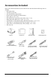
Accessories Included Remove the main unit and the accessories from the box and check that the following items are included. • Quick Start Guide • ViewSonic wizard CD • Lens cap (affixed to the projector) • Remote control (includes one button battery) • Power cable (1.8 m / 5.9 ft) • DVI / Mini D-sub 15-pin conversion cable (19 cm / 7.5 in ) • RGB signal cable (Mini D-sub 15-pin, 2 m / 6.6 ft ) • S-Video cable (3.5 mm diameter plug / Mini DIN 4-pin plug, 1.5 m / 4.9 ft ) • Video cable (3.
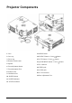
Projector Components 1. Lens 13. MENU button 2. Lens cap 14. SOURCE button / Cursor 3. Focus ring 15. AUTO button / Cursor 4. Remote control sensor 16. QUICK MENU button / Cursor 5. Speaker 6. Front Adjustment button 7. Front Adjustment Foot 8. Exhaust vents 9. Ventilation slots 10. POWER button 11. POWER indicator 12. STATUS indicator 3 ViewSonic PJ250 17. PC connector 18. VIDEO jack 19. AUDIO jack 20. AC IN connector 21.
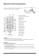
Remote Control Components Before use, pull out and remove the transportation insulation sheet which is inserted in the battery compartment. 1.Infrared transmitter 2.POWER ON and OFF buttons 3.FREEZE button 4.MUTE button 5.PIP button 6.Input selection Buttons 7.ASPECT button 8.QUICK button 9.AUTO button 10.MENU button 11.CANCEL button 12.Cursor Buttons 13.ENTER button 14.HKSTN button 15.VKSTN button 16.ZOOM button 17.VOL button 18.+/- Buttons CAUTION • Danger of explosion if battery is incorrectly replaced.
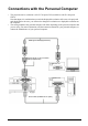
Connections with the Personal Computer • The projectors native resolution is 1024 X 768 pixels XGA,scalable to 1280 X 1024 pixels SXGA. Note that input of a resolution that exceeds the displayable resolution will cease to be projected and should this be the case, you will need to change the resolution to a displayable resolution on the computer. • The setting method of the personal computer will differ depending on the personal computer that you are using.
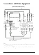
Connections with Video Equipment Component cable (Available as an option) (3.5 mm diameter, 4 Pde, Plug to RCA X 3) Video cable (Supplied item) Blue Red Green S-Video cable (Supplied item) Component Component White DVI/mini D-sub 15-pin conversion cable (Supplied item) Green Red Red Blue Audio cable (Supplied item) Component cable (Available as an option) (D-sub 15-pin to RCA 3) Note: • This projector's video cable and S-video cable are unique cables.
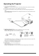
Operating the Projector 1 Set up the screen and the projector See the affixed "Projection Distance Table" for the desired distance between the screen and the projector. 2 Connect the personal computer or video equipment to the projector. 3 Connect the AC IN connector of the projector and the power outlet using the supplied power cable. The POWER indicator will light amber, the cooling fan will rotate at low speed, and the unit will enter the standby mode.
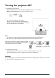
Turning the projector Off 1 Switch the power button off. Main unit operation: Press and hold the POWER button for several seconds. Remote control operation: Press the POWER OFF button. The "Power off" indication will appear. When the red bar extends fully (approximately 5 seconds), the projection screen will turn off and the unit will enter the power off operation. Note • The operation can be cancelled by pressing a button other than the POWER button.
Using the Quick Menu Note that the Quick Menu will not be displayed unless the signal of the connected equipment is detected. Please select the input that you wish to adjust. Main unit operation (1) Press the QUICK MENU button to access the Quick Menu. Press again to select the desired adjustment display. (2) Press the or button to adjust. (3) To close the display immediately, press the MENU button. In the absence of operations for a period of about 10 seconds, the display will close automatically.
Menu Operation Remote Control MENU button Used for menu display and menu closure. CURSOR(STWX) button Selects menu names and item names as well as in setting and adjusting the item contents. CANCEL button Returns to menu name selection as well as to close the menu (and the sub menu display). ENTER button Sets the verification display. Projector MENU button Displays menu, to return to menu name selections, and to close menus (i.e. closing sub menu displays).
On Screen Display Cursor The setting/adjustment of the cursor position can be adjusted. Menu title Menu Selections (Item name) Sub Selections (Item name) Adjustment bar setting contents Adjustment bar: Indicates the adjustment condition by increasing or decreasing in bar length setting contents: Displays the set contents Icon: Displays the sub menu or setting contents • The remote control should be pointed toward the remote control sensor of the projector and operated.
Menu Selection 2 Press the cursor (WX) button to select the menu item you wish to adjust. Each press of the cursor (X) button advances the selection one step in the sequence of "Color" →"View" →"Setup" →"Info." →"Image". Each press of the cursor (W) button causes a return of one step. The selected menu name will appear in red. Note : To cancel the display of the cursor, press the CANCEL button on the remote control or the MENU button on the projector.
STATUS Indicator Light STATUS indicator STATUS Indicator POWER Indicator POWER indicator Problem Flashes red (0.5 s lit /0.5 s off) Lit red The temperature has become abnormally high. The thermal protector is activated. if the room temperature is high, move the projector to a cool location. If the internal temperature of the projector is high, check the ventilation holes of the cooling fan and clean them if they are obstructed.
Replacing the Lamp Cartridge WARNING • The Lamp Cartridge should only be replaced after the unit has been turned off, cooled down for 60 minute and the power cord has been unplugged. Replacement of the lamp cartridge during operation or immediately after operation stops may cause burns due to high temperature. • Do not remove any screws other those specified. • Do not touch the lamp with bare hands. Doing so could shorten the life of the lamp.
4 Remove the lamp cartridge. (1) Turn the 2 screws that fasten the lamp cartridge counterclockwise until they turn freely. (The screws will not come out.) (2) Grasp the handle of the lamp cartridge, pull it upward and remove the lamp cartridge. 5 Install the new lamp cartridge. (1) Slowly push in the lamp cartridge with the socket facing forward. (Align the lamp cartridge screw with the screw hole of the projector.) (2) Turn the 2 screws of the lamp cartridge clock-wise to tighten.
Specifications Optical DMD Lamp Image size Electrical Inputs Color Reproduction Resolution Input Current Power Requirement Power Consumption Mechanical Dimensions Excluding Stand Weight Operational Temperatures Regulations Single Chip Digital Micro Device (DMD) 1024 x 768 dots, scaling to 1280 x 1024 120 W high-pressure mercury lamp 36 inch to 200 inch Video (NTSC3.58/NTSC4.
Distance Chart Width Height Diagonal Throwing Distance Screen Bottom Lens Center Projector distance from screen Screen Size (D) 17 (W) x (H) (L) (B) inch mm mm mm inch inch mm inch mm inch 36 914 732 x 549 28.8 x 26.1 1200 47.2 95 3.7 40 1016 813 x 610 32 x 24 1320 52.0 105 4.1 60 1524 1219 x 914 48 x 36 1990 78.3 157 6.2 80 2032 1626 x 1219 64 x 48 2650 104.3 209 8.2 100 2540 2032 x 1524 80 x 60 3310 130.3 262 10.3 120 3048 2438 x 1829 96 x 72 3970 156.3 314 12.
Cabinet Dimensions ViewSonic PJ250 18
Customer Support For technical support or product service, please contact ViewSonic. NOTE: You will need the product serial number. Country/Region Web site T = Telephone F = FAX Email United States viewsonic.com/ support T: (800) 688-6688 F: (909) 468-1202 service.us@ viewsonic.com Canada viewsonic.com/ support T: (800) 688-6688 F: (909) 468-1202 service.ca@ viewsonic.com United Kingdom viewsoniceurope.com T: 0800 833 648 F: (01293) 643910 service.eu@ viewsoniceurope.
WARRANTY VIEWSONIC PROJECTOR What the warranty covers: ViewSonic® warrants its products to be free from defects in material and workmanship during the warranty period. If a product proves to be defective in material or workmanship during the warranty period, ViewSonic will at its sole option repair or replace the product with a like product. Replacement product or parts may include remanufactured or refurbished parts or components.
Appendix Power Cord Safety Guidelines Caution: Use a power cable that is properly grounded. Always use an AC power cord that meets your country’s safety standard. USA .............................. UL Canada......................... CSA Germany....................... VDE Switzerland ...................SEV Britain............................BASE/BS AC PLUG CORD PRECAUTIONS FOR THE UNITED KINGDOM FOR YOUR SAFETY PLEASE READ THE FOLLOWING TEXT CAREFULLY.
IMPORTANT SAFETY INFORMATION Important Safeguards These safety instructions are to maximize the long life of the unit and prevent fire and shock. Please read carefully. Installation • • • • • Place the unit on a flat, level surface in a dry area away from dust and moisture. Do not place the unit in direct sunlight, near heaters or heat radiating appliances. Exposure to direct sunlight, smoke or steam can harm internal components. Handle the unit carefully.
Compliance Information for U.S.A. This equipment has been tested and found to comply with the limits for a Class A digital device, pursuant to part 15 of the FCC Rules. These limits are designed to provide reasonable protection against harmful interference. This equipment generates, uses, and can radiate radio frequency energy, and if not installed and used in accordance with the instructions, may cause harmful interference. WARNING This is a class A product.