Service Manual ViewSonic VA902-3 VA902b-3 Model No. VS10715 19” Color TFT LCD Display (VA902-3_VA902b-3_SM Rev. 1a Jun.
Copyright Copyright © 2006 by ViewSonic Corporation. All rights reserved. No part of this publication may be reproduced, transmitted, transcribed, stored in a retrieval system, or translated into any language or computer language, in any form or by any means, electronic, mechanical, magnetic, optical, chemical, manual or otherwise, without the prior written permission of ViewSonic Corporation.
TABLE OF CONTENTS 1. Precautions and Safety Notices 1 2. Specification 4 3. Front Panel Function Control Description 7 4. Circuit Description 14 5. Adjustment Procedure 18 6. Troubleshooting Flow Chart 40 7. Recommended Spare Parts List 43 8. Exploded Diagram and Exploded Parts List 53 9. Block Diagram 58 10. Schematic Diagrams 59 11.
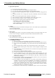
1. Precautions and Safety Notices 1. Appropriate Operation (1) (2) (3) (4) (5) (6) (7) (8) (9) Turn off the product before cleaning. Use only a dry soft cloth when cleaning the LCD panel surface. Use a soft cloth soaked with mild detergent to clean the display housing. Disconnect the power plug from AC outlet if the product is not used for a long period of time. If smoke, abnormal noise, or strange odor is present, immediately switch the LCD display off.
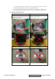
The LCD module should be supplied by power complied with requirements of Limited Power Source (IEC60950 or UL1950), or be applied exemption. (14) The LCD module is designed so that the CFL in it is supplied by Limited Current Circuit (IEC60950 or UL1950). Do not connect the CFL in Hazardous Voltage Circuit. 5.2. Handling and Placing Methods Correct Methods: Incorrect Methods: Only touch the metal frame of the LCD panel Surface of the LCD panel is pressed by fingers or the front cover of the monitor.
Place the monitor on a clean and soft foam pad. Placing the monitor on foreign objects. That could scratch the surface of the panel or cause “Mura” The panel is placed facedown on the lap.
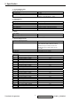
2. Specification 1. General Requirements General Specifications Test Resolution & Frequency Test Image Size Contrast and Brightness Controls “1280 x 1024” @ 60Hz Full Size Factory Default: Contrast = 70%, Brightness = 100% 2. Signal Interface Video Interface Analog Input Connector Default Input Connector Video Cable Connector DB-15 Pin out Video Signals Video Impedance Exclusions DB-15 (Analog) Defaults to the first detected input Compliant DDC 1/2B. 1.
23 24 25 26 1152 x 870 @ 75Hz, 68.7kHz 1280 x 1024 @ 60Hz, 63.4kHz 1280 x 1024 @ 75Hz, 79.97kHz 1280x 720 @ 60Hz, 45kHz (HDTV) Yes Yes Yes Yes Changing Modes Maximum Mode Change Blank Time for image Under 5 seconds (Maximum) stability. Note: 1 seconds (Typ.) for recognized timings 1) Excluding “Auto Adjust” time 1-2 seconds (Typ.) for unrecognized timing 2) Under DOS mode (640 x 350, 720 x 400 & 640 x 400), there is no “Auto Adjust” feature.
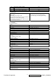
6. Mechanical Dimensions Width Height Depth Monitor Weight 414 mm 407 mm 219 mm 5.4kg / 11.88 lbs Ergonomics Tilt Up Tilt Down 20 DEGREES MINIMUM -5 degrees Package Specifications Width Height Depth Gross Weight 490 mm 570 mm 145 mm 6.8kg (14.96lb) 7.
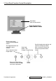
3. Front Panel Function Control Description Main Menu With OnView controls Front Control Panel shown below in detail Displays the control screen for the highlighted control. Also toggles between two controls on some screens. Also a shortcut to Auto Image Adjust. Scrolls through menu options and adjusts the displayed control. Power light Green = ON Orange = Power Saving Displays the Main Menu or exits the control screen and saves adjustments.
Do the following to adjust the screen image: 1 To display the Main Menu, press button [1]. Main Menu AUTO SET Auto Adjust Contrast/Brightness Color Adjust i Information Image Adjust ? Setup Menu Memory Recall 1:EXIT 2:SELECT NOTE: All OnView menus and adjustment screens disappear automatically after about 15 seconds. This time period is adjustable through the Setup menu and the OSD timeout control described on page 11.
Main Menu Controls Adjust the menu items shown below by using the up I and down J buttons. Control Explanation Auto Adjust automatically sizes, centers, and fine tunes the video signal to eliminate waviness and distortion. Press the [2] button to obtain a sharper image. NOTE: Auto Adjust works with most common video cards. If this function does not work on your LCD dislay, then lower the video refresh rate to 60 Hz and set the resolution to its pre-set value.
Control Explanation User — Individual adjustments for red, green, and blue. 1 2 3 i To select color (R, G or B) press button [2]. To adjust selected color, press I or J. When you are finished making all color adjustments, press button [1] twice. Information displays the timing mode (video signal input) coming from the graphics card in your computer. See your graphic card’s user guide for instructions on changing the resolution and refresh rate (vertical frequency).
Control Explanation Fine Tune sharpens focus by aligning the illuminated text and/ or graphic characters. NOTE: Try the Auto Adjust (see page 9) before using the Fine Tune control. Sharpness adjusts the clarity and focus of the screen image. ? Setup Menu displays the menu shown below. The Setup Menu controls are explained below. Language Select allows you to choose the language used in the menus and control screens. Resolution Notice advises the optimal resolution to use.
Control OSD Explanation OSD Background allows you to turn the On-Screen display background on or off. This means that while making adjustments from the OSD control screens you can also view open software applications, or the Windows desktop. Memory Recall returns adjustments to the original factory settings if the display is operating in a factory Preset Timing Mode listed in this user guide.
Short Cut Key Function Key : 5 Keys ! [1] [2] [▼ ▼] or [▲ ▲] 1 2 ▼ ▲ Main Menu Auto Image Adjust to immediately activate Contrast menu. It should be change to Brightness OSD by push button [2]. [▼ ▼] + [▲ ▲] recall Contrast or Brightness while in the Contrast or Brightness adjustment, or recall both of Contrast and Brightness when the OSD is not open. [1] + [2] toggle 720x400 and 640x400 mode when input 720x400 or 640x400 mode. [1] + [▼ ▼] + [▲ ▲] White Balance.
4. Circuit Description A. Scaling controller GENERAL DESCRIPTION The TSU16AS is total solution graphics processing IC for LCD monitors with panel resolutions up to SXGA. It is configured with a high-speed integrated triple-ADC/PLL, a high quality display processing engine, and an integrated output display interface that can support LVDS panel interface format.
Copyright c 2004 MStar Semiconductor, Inc. All rights reserved.
Input Current, High (IIH) -1.0 uA Input Current, Low (IIL) 1.0 uA Input Capacitance 5 pF DIGITAL OUTPUTS Output Voltage, High (VOH) VDDP-0.1 V Output Voltage, Low (VOL) 0.1 V DYNAMIC PERFORMANCE Analog Bandwidth, Full Power 250 MHz Channel to Channel Matching 0.5% Full-Scale Specifications are subjected to change without notice. TSU16AS SXGA LCD Controller with Analog Interface and Dual LVDS Transmitter Preliminary Data Sheet Version 0.2 Version 0.2 - 7 - 10/1/2004 Copyright c 2004 MStar Semiconductor, Inc.
• Two clock output ports • Two external interrupts, INT1 is shared with Slave IIC interrupt source • Maximum 4 channels of 6-bit ADC • Flash-ROM code protection selection • Hardware ISP (In System Programming), no Boot Code required • Embedded Dual Ports DDCRAM (128-byte x 2) • Green products like Pb-Free Packages or All Green Packages available PIN CONFIGURATION & DESCRIPTION A “CMOS output pin” means it can sink and drive at least 4mA current. It is not recommended to use such pin as input function.
5. Adjustment Procedure 1. Function Test 1.1. Product - 19” LCD Monitor 1.2. Test Equipment - Color Video Signal & Pattern (or PC with SXGA resolution and a sound card) 1.3. Test Condition Before function test and alignment, each LCD Monitor should be run-in and warmed up for at least 30 minutes with the following conditions: (a) In room temperature, (b) With full-white screen, RGB, and Black (c) With cycled display modes, 640*480 (H=43.27kHz, V=85Hz) 800*600 (H=53.7kHz, V=85Hz) 1024*768 (H=68.
1.4.2 Function Test Display Pattern Item Test Content 1 Frequency & Tracking 2 Contrast/Brightness 3 4 5 6 7 Pattern Fine Line Moire Specification Eliminate visual wavy noise. 16 Gray Scale 16 gray levels should be distinguishable. Boundary Horizontal & Vertical Horizontal and Vertical position of video should be Thickness adjustable to be within the screen frame. RGB Color RGB Color Contrast of each R, G, B, Performance Intensities color should be normal.
G. Color Pattern (Figure5) B. Color Pattern (Figure 6) Full White Patter (Figure 7) Dark Screen Pattern (Figure 8) Black-White Pattern (Figure 9) 1.5. Function Test and Alignment Procedure 1.5.1 All Modes Reset You should do “All Mode Reset” (Refer to Chapter III-3. Hot Keys for Function Controls) first. This action will allow you to erase all end-user’s settings and restore the factory defaults. 1.5.
1.5.3 Firmware Test Pattern: Burn In Mode (Refer to Chapter III-3. Hot Keys for Function Controls) - Make sure the F/W is the latest version. 1.5.4 DDC Test Pattern: EDID program - Make sure it can pass test program. 1.5.5 Fine Tune and Sharpness Test Signal: 1280*1024@60Hz Test Pattern: Line Moire Pattern - Check and see if the image has noise and focus performs well. Eliminate visual line bar.
F. Adjust Color Temperature: (1) EEPROM INIT (5 BLOCKS): Press “▼” key move cursor to EEPROM INIT, Press “ 2 ” key then monitor will INIT ADC value. (2) Press “▲” key move cursor to “White Balance”, Press “ 2 ” key do white balance adjustment. (3) Press “▼” key move cursor to “Color Temperature Adjust”, Press “ 2 ” key, Then OSD will display Fig.2 (Fig.2) (4) 9300K verify: move cursor to 9300K Press “ 2 ” key. Press “▼”, “▲” key adjust R.G.B value x=0.283 ± 0.02 y=0.298 ± 0.
1.5.10 Dead Pixel and Line Test Signal: 1280*1024@60Hz Test Pattern: Dark and White Screen Pattern - Check and see if there are dead pixels on LCD panel with shadow gauge and filter film. - The total numbers and distance of dead pixels should be compliant with the spec. 1.5.11 Mura Test Pattern: White, RGB, Black, & Grey Test Tool: 8% ND Filter - Check if the Mura can pass 8% ND Filter. 1.5.
2. Firmware Upgrade Procedure When you receive the returned monitor, please check whether the firmware version is the latest. If not, please do the following procedures to upgrade it to the latest version. 2.1.
2.2. Setup Procedure 2.2.1 Connect P2 of Fixture with printer port of PC by LPT Cable. 2.2.2 Connect P1 of Fixture with VA902/b-3 Monitor by VGA Cable. 2.2.4 Connect Power Cord to VA902/b-3 Monitor. 2.2.5 Connect PC to the additional monitor. 2.3. ISP Download program procedure 2.3.1 Hardware Connect status: 2.3.2 Down load isp program Step 1: ViewSonic Corporation Execute ISP.
Step 2: Select MCU type Pressing the Comb box to select the type of the MCU, It need to be selected the MTV512GM64 for this project. Then press the Create Security File Button to enter step 3. Step 3: Create Security File Enter the three string into the blank like fig 2. Then press OK Button.
Step 4: Load file Press the Load MCU File button to select the file will be download. (*.hex) Step 5: Run Pressing the Run Button to start download program. Press OK button to Enter ISP mode.
Step 6: Download program finish Pressing the OK Button to finish the download program procedure. Trouble shooting: If you find the status like the follow picture. Please check the following item. a. The connecting status between PC and ISP board. b. The connecting status between ISP status and Monitor. Turn off the power of monitor (AC plug off ) and disconnect the D-Sub connector . To connect the D-Sub connector and then turn on the power of monitor.
3. DDC Key In Procedure Note: 1. Every time after replacing the main board, you have to do the DDC key in. 2. If you find the DDC does not conform to the monitor, you have to do the DDC key in. 3.1.
3.2. Setup Procedure 3.2.1 Connect VGA Card and DDC Card with RS-232 cable. 3.2.2 Barcode Reader connect with keyboard and PC keyboard port. 3.2.3 Connect RS-232 Cable and VA902(3) with VGA Cable. (when key in DVI DDC information, use VGA transform to DVI port ) 3.2.4 Connect Power Cord to VA902(3) Monitor. 3.3. DDC Key In Procedure 3.3.1 Run DDC.exe 3.3.2 Choose model number and conform the Time then Press “ENTER” key.
3.3.3 When appear the PIC “ choose DDC Card”, Press ALT+2 Enter DDC 2B test interface. Choose DDC Card 3.3.4 Press F8 to choose corresponding model.DAT (VA902(3).
3.3.5 Press F9 enter the download interface 3.3.6 Key in the serial number or use the barcode reader to scan the barcode of the monitor, and press “ENTER” key.
3.3.7 The successful picture is as follows. ”Compare EDID :OK! Press any key to continue”. 3.3.
3.4. Check Method Use ViewSonic EDID Editor Connect the VA902(3) to PC with VGA Cable. Excute the EDID Editor, then Press Ctrl+F5.
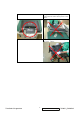
Packing For Shipping And Disassembly Procedure Packing For Shipping 1. Packing Procedure 1.1 Paste protection film to protect the monitor. (Figure 1) 1.2 Put the monitor in the PE bag and seal the bag with tape. (Figure 2) Figure 1 Figure 2 1.3 Put the cushions on the monitor. (Figure 3) 1.4 Place the monitor into the carton and then put all the accessories into the carton. At last, close the carton and seal it with tape.
Disassembly Procedure 1. Disassembly of Stand unit from Monitor 1.1 Remove two Hinge Cover. 1.2 Unscrew four screws that secure Stand Unit. 1.3 Detach Stand Unit from the monitor.
2. Disassembly of Front Cover and Rear Cover 2.1 Unscrew two screws that secure Rear Cover to remove Front Cover. 2.2 Unscrew 2 screws to remove Rear Cover.
3. Disassembly of Hinge, Main Board, Keypad Board and Panel Unit 3.1 Unscrew 4 screws to remove Hinge. Hinge 3.2. Unscrew 2 screws to remove Shielding Plate. Shielding Plate 3.3. Unscrew 2 screws and disconnect the connector to remove VGA Cable. VGA Cable 3.4. Unscrew 7 screws and disconnect the wires to remove Main Board.
3.5. Lay Panel Unit facedown and unscrew 4 screws on its right and left sides to remove Panel Unit and Keypad Board.
6. Troubleshooting Flow Chart START CHECK MAIN BOARD 5V OK? N CHECK POWER OARD OK? CHECK I102 AND ROUND CAP OK? N CHECK I104, SUROUND CAP BEAD OK? CHECK I104 3.3V UROUND CAP OK? N CHECK I103, SUROUND CAP BEAD OK? CHECK I103 1.8V UROUND CAP OK? Y 3.3V OK? Y 1.
6.1. NO POWER CHECK 5V O/P T801 POWER STAR CHECK I902 CHECK P901~P904 12V PANEL CHECK I901 Q905, Q911 Q907, Q908 Q909, Q910 CHECK 12V O/P C823 Y CHECK F801 D801 C805 CHECK D823 D822 CHECK I801 Q801 5V CHECK T901, T902 12V MAIN BOARD 6.2. MCU NO FUNCTION CHECK CHECK N C123,R125,D107 RESET CHECK N CHECK VCC5V L804,D823,D822 OK? CHECK OK? I102 N Y CHECK PIN40 D109,D110,D112 3.
6.3. NO DISPLAY Power key N Work ok Check N N Check Check 5VMCU Keypad I102 Y Check N H V sync Check N Check Check N P101 I101 I/O cable Y Check R.G.B N DATA Check N Check Check N I101 I/O cable P102 Y Check N Check N C126,C127 X101 Check Check N VCC2.5V,3.3v I101,I102 Y Check I101 N HS,VS Check N SCL,SDA Check SCL,SDA I102, N Check SCL,SDA I105, HWRESET Y Check N Check N N Check P102 WIRE Q102 BACKLITE Check PANEL 6.4.
7. Recommended Spare Parts List RECOMMENDED SPARE PARTS LIST (VA902-3) ViewSonic Model Number: VS10715 Serial No. Prefix: QAK G- Model Item 1 2 3 4 5 6 7 8 9 10 11 12 13 14 15 16 17 P - Model Item 1 Rev: 1a ECR/ECN Plastics: Description POWER CORD CHINA WALL 1.83M BLACK GUARANT CARD VIEWSONIC VA902-3 QSG CD-OWNER GUIDE VA902B-3 WIZARD VS10715 HSD PCB ASS'Y BLOCK (MAIN) PCB ASS'Y BLOCK (CON) BEZEL ASS'Y ABS 94HB PS-7604B VA902 CABI BACK ASSY VE910 ABS 94HB BLACK 4001 I/O CABLE D15/C13 20276(4.5) 1.
BOM LIST (VA902-3) ViewSonic Model Number: VS10715 Rev: 1a Serial No.
Item 106 107 108 109 110 111 112 113 114 115 116 117 118 119 120 121 122 123 124 125 126 127 128 129 130 131 132 133 134 135 136 137 138 139 140 141 142 143 144 145 146 147 148 149 150 151 152 153 154 155 156 157 158 159 160 161 162 163 164 165 166 167 168 169 170 171 172 173 174 175 176 177 178 179 180 181 182 183 184 185 186 187 188 189 190 191 192 193 194 195 196 197 198 199 200 201 202 203 204 205 206 207 208 209 210 211 212 213 214 215 ViewSonic P/N E-C-0404-1834 N/A N/A E-00003250 N/A E-00003252 N/A
Item 216 217 218 219 220 221 222 223 224 225 226 227 228 229 230 231 232 233 234 235 236 237 238 239 240 241 242 243 244 245 246 247 248 249 250 251 252 253 254 255 256 257 258 259 260 261 262 263 264 265 266 267 268 269 270 271 272 273 274 275 276 277 278 279 280 281 282 283 284 285 286 287 288 289 290 291 292 293 294 295 296 297 298 299 300 301 302 303 304 305 306 307 308 309 310 311 312 313 314 315 316 317 318 319 320 321 322 323 324 325 ViewSonic P/N M-WR-0828-0455 M-WR-0828-0451 M-WR-0828-0450 M-WR-08
Item 326 327 328 329 330 331 332 333 334 335 336 337 338 339 340 341 342 343 344 345 346 347 348 349 350 351 352 353 354 355 356 357 358 359 360 361 362 363 364 365 366 367 368 369 370 371 372 373 374 375 376 377 378 379 380 381 382 383 384 385 386 387 388 389 390 391 392 393 394 395 396 397 398 399 400 401 402 403 404 405 406 407 408 409 410 411 G Model Item 1 2 3 4 5 ViewSonic P/N E-R-0405-2306 N/A N/A E-R-0405-3235 E-R-0405-2818 N/A E-R-0405-0063 N/A E-R-0405-3034 N/A E-R-0405-1171 E-R-0405-3221 E-R-04
BOM LIST (VA902b-3) ViewSonic Model Number: VS10715 Rev: 1a Serial No.
Item 96 97 98 99 100 101 102 103 104 105 106 107 108 109 110 111 112 113 114 115 116 117 118 119 120 121 122 123 124 125 126 127 128 129 130 131 132 133 134 135 136 137 138 139 140 141 142 143 144 145 146 147 148 149 150 151 152 153 154 155 156 157 158 159 160 161 162 163 164 165 166 167 168 169 170 171 172 173 174 175 176 177 178 179 180 181 182 183 184 185 186 187 188 189 190 191 192 193 194 195 196 ViewSonic P/N E-C-0404-1855 N/A E-C-0404-2262 E-C-0404-4833 N/A E-C-0404-1838 E-C-0404-1833 N/A E-C-0404-1
Item 197 198 199 200 201 202 203 204 205 206 207 208 209 210 211 212 213 214 215 216 217 218 219 220 221 222 223 224 225 226 227 228 229 230 231 232 233 234 235 236 237 238 239 240 241 242 243 244 245 246 247 248 249 250 251 252 253 254 255 256 257 258 259 260 261 262 263 264 265 266 267 268 269 270 271 272 273 274 275 276 277 278 279 280 281 282 283 284 285 286 287 288 289 290 291 292 293 294 295 ViewSonic P/N M-WR-0828-0460 M-WR-0828-0450 M-MS-0808-0856 M-WR-0828-0460 M-WR-0828-0478 M-WR-0828-0478 M-WR-0
Item 296 297 298 299 300 301 302 303 304 305 306 307 308 309 310 311 312 313 314 315 316 317 318 319 320 321 322 323 324 325 326 327 328 329 330 331 332 333 334 335 336 337 338 339 340 341 342 343 344 345 346 347 348 349 350 351 352 353 354 355 356 357 358 359 360 361 362 363 364 365 366 367 368 369 370 371 372 373 374 375 376 377 378 379 380 381 382 383 384 385 386 387 388 389 390 391 392 393 394 395 396 ViewSonic P/N E-R-0405-3211 E-R-0405-3211 E-R-0405-0645 E-R-0405-2367 E-R-0405-3213 E-R-0405-3214 E-R-
Item 397 398 399 400 401 402 403 404 405 406 407 408 409 410 411 ViewSonic P/N N/A N/A N/A N/A E-00003308 N/A E-00004574 N/A E-X-0415-0119 N/A N/A N/A N/A N/A N/A P model Item 1 ViewSonic P/N A-00003623 G Model Item 1 2 3 4 5 ViewSonic P/N A-PC-0106-0277 DC-00003461 M-LB-0813-0862 M-LB-0813-0863 M-LB-0813-0864 Ref.
8.
ViewSonic Corporation 54 Confidential - Do Not Copy VA902-3_VA902b-3
8. Exploded Diagram and Exploded Parts List EXPLODED PARTS LIST (VA902-3) Item 1-1 1-2 2 3 4 5 6 7 8 9 10 11 12-1 12-2 13-1 13-2 14 15 16 17 18 19 20 21 22-1 22-2 23 24 25 26 27 28 ViewSonic Model Number: VS10715 Rev: 1a Serial No.
EXPLODED PARTS LIST (VA902b-3) ViewSonic Model Number: VS10715 Item 1-1 1-2 2 3 4 5 6 7 8 9 10 11 12-1 12-2 13-1 13-2 14 15 16 17 18 19 20 21 22-1 22-2 23 24 25 26 27 28 Rev: 1a Serial No.
PACKING PART LIST ( VA902-3 ) Item 1 2 3 4 5 6 7 7 7 8 9 9 9 10 ViewSonic Model Number: VS10715 Rev: 1a ViewSonic P/N N/A M-MS-0808-1317 P-00003014 P-00003015 DC-00005835 DC-00005834 A-PC-0106-0138 A-PC-0106-0277 A-00003623 N/A N/A N/A N/A N/A Ref.
9. Block Diagram AC INPUT 100V-200V SW POWER SUPPLY I801 12V D822,D823 T801 5V INVERTER I901 PANEL DISPLAY VLCD Q102 D919,D910 Q901 3.3V I104 SCALAR I101 1.8V I103 X101 SYNC R111 R113 H,V SYNC VGA D-SUB P101 SCL,SDA VGA 5V ViewSonic Corporation MCU I102,DDC R,G,B INPUT EEPROM I105 58 3.
10. Schematic Diagrams 10.1.
10.2. VGA INPUT VCC_3v3 PC5V ( 6 ) P101 GND R R-GND G G-GND B B-GND +5V GND VGA-HS VGA-VS DDC-SDA DDC-SCL 13 12 11 10 9 8 7 6 5 4 3 2 1 D101 D103 D105 1N4148 1N4148 1N4148 RED+ R104 47 C101 0.047uF GREEN+ GREENBLUE+ R106 47 C103 0.047uF R108 47 C105 0.047uF RED- BLUE- GIN ( 4 ) BIN ( 4 ) PC5V Z105 5.6V D104 D106 D102 1N4148 1N4148 1N4148 R101 75 R102 75 JST-PH13P-2.0-90 H_Sync R111 R110 2.2K 47 C102 0.047uF R107 47 C104 0.047uF R109 47 C106 0.047uF Z102 5.
10.3. SCALER VDDC RINP RINM SOGIN0 GINP GINM BINP BINM ( 3 ) VSYNC ( 3 ) HSYNC 9 8 VSYNC HSYNC 54 32 55 VDDC VCTRL ( 3 ) GIN ( 3 ) GNDG ( 3 ) BIN ( 3 ) GNDB 19 18 17 16 15 14 13 ( 3 ) RIN ( 3 ) GNDR VDDC 30 53 AVDD AVDD I101 VDDP VDDP VDDP 12 20 AVDD LVA3P LVA3M LVACKP LVACKM LVA2P LVA2M LVA1P LVA1M LVA0P LVA0M 33 34 35 36 37 38 39 40 41 42 PA0 PA1 PA2 PA3 PA4 PA5 PA6 PA7 PA8 PA9 VCC_1v8 L103 3.5X9*0.8 VDDC 2 VCC_1v8 PA[0..9] C116 PA[0..9] ( 5 ) + 0.
10.4. PANEL INTERFACE VLCD L105 3.5X9*0.8 C121 0.1uF + C120 100uF/16V 30 29 28 NC27 NC26 NC25 24 RXO3+ 23 RXO322 RXOC+ 21 RXOC20 RXO2+ 19 RXO218 17 RXO1+ 16 RXO115 14 RXO0+ 13 RXO012 RXE3+ 11 RXE310 RXEC+ 09 RXEC08 07 RXE2+ 06 RXE205 RXE1+ 04 RXE103 RXE0+ 02 RXE001 R121 R120 R119 ( 4 ) PA[0..9] ( 4 ) PB[0..9] PA[0..9] PB[0..
10.5. MCU PC5V (3) VCC5V PC5V D109 1N4148 VCPU D112 D110 1N4002 8 7 6 5 VCPU C124 47uF/16V + ( 4 ) TCLK C125 RP02 10K RP03 10K 1 2 3 4 0.1uF I102 1N4148 18 X2 19 X1 VCPU 9 C128 R128 RST 12 ( 4 ) INT P3.2/INT0 0.1uF A0 A1 A2 GND VCC WP SCL SDA 8 7 6 5 24C16 EXIT MINUS PLUS MENU LED_G POWER LED_A VCC5V R177 NC 13 14 15 1 2 3 4 5 6 7 8 P3.3/INT1 P3.4/T0 P3.5/T1 P7.6/CLKO P5.0/DA0 P7.7 P5.1/DA1 P5.2/DA2 P5.3/DA3 HSDA1/TXD0/P3.1 P5.4/DA4 HSCL1/RXD0/P3.0 P5.5/DA5 HSCL2/P5.
10.6. KEY PAD P701 1 JST-PH8P-2.
10.7. A/D POWER C813 3300pF/500V R843 511K/1206 R806 511K/1206 R839 NC D806 UF4007 R839 1 1.2M/1/4WS 1.2M/1/4WS L803 5.2uH + 10 L804 JUMPER SR306 D823 + R853 12R/1/4WS L806 BEAD D807 1U4G 4 12 5 7,8 C824 + 1000UF/10V D822 SR306 C831 4700PF 1N4148 R846 820/1/4WS + C809 R828 L801 BEAD 8 2 FB VDD 7 Sense 6 RT 5 3 VIN 4 RI R832 C811 C845 0.1uF/50V R811 0.75R/ 2WS C801 0.
10.8. INVERTER 2374301105>2374301204 D901 short and I902 open 1,2 BEAD 1 C902 3,4 C903 VCC12V R906 1000P 5,6 10 R907 10 C904 22P,3KV 10 470uF/16V 5 6 7 + Q905 AP9977GM D903 1N4148 C908 C925 0.1uF C915 4 JUMPER JUMPER 1N4148 C909 R909 R910 NC 1 SST 2 CT ISEN 8 VSEN 7 R921 D908 GNDA VCCA 6 5.1K 1N4148 4 DRV2 5 C914 0.01uF I901 C912 27P C913 330P R924 D917 R914 D909 SB140 3 DRV1 C910 R918 0.
11. PCB Layout Diagrams 11.1.
11.2.
11.3.
11.4.
* Reader’s Response* Dear Readers: Thank you in advance for your feedback on our Service Manual, which allows continuous improvement of our products. We would appreciate your completion of the Assessment Matrix below, for return to ViewSonic Corporation. Assessment A. What do you think about the content of this Service Manual? Unit Excellent Good Fair Bad 1. Precautions and Safety Notices 2. Specification 3. Front Panel Function Control Description 4. Circuit Description 5. Adjustment Procedure 6.