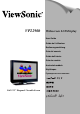
VP2290b Widescreen LCD Display User Guide Guide de l’utilisateur Bedienungsanleitung Guía del usuario Guida dell'utente Guia do usuário Användarhandbok Käyttöopas Jmdh\h^kl\h ihevah\Zl_ey Full 22.
Contents For Your Records ........................................................................................................ 1 Before setting up................................................................................................................ 2 Prerequisites................................................................................................................ 2 Unpacking..............................................................................................................
Compliance ......................................................................................................................34 Compliance Compliance Information for U.S.A. .......................................................34 Industry Canada Class A Emission Compliance Statement .............................................34 Avis de Conformité àla Réglementation d’Industrie Canada ............................................34 European Union – EMC Directive ........................................
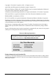
Copyright © ViewSonic Corporation, 2003. All rights reserved. Apple, Mac and ADB registered trademarks of Apple Computer, Inc. Microsoft, Windows, Windows NT, and the Windows logo are registered trademarks of Microsoft Corporation in the United States and other countries. ViewSonic, the three birds logo and OnView are registered trademarks of ViewSonic Corporation. VESA and SVGA are registered trademarks of the Video Electronics Standards Association. DPMS and DDC are trademarks of VESA.
Before setting up This manual contains information on how to set up and operate the ViewSonic VP2290b LCD Display, hereafter called the display. This chapter describes the following: • Prerequisites • Unpacking • Checking parts Prerequisites You will need a personal computer or a workstation (hereafter called the computer) with the following.
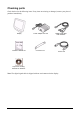
Checking parts Check the box for the following items. If any items are missing or damaged, contact your place of purchase immediately. Display ViewSonic Wizard CD Power adapter and cord Connector tool Digital signal cable P/N: 07N2227 Power cord Liquid View Scaling Software for Windows Note: The digital signal cable is shipped with one end connected to the display.
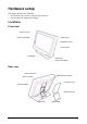
Hardware setup This chapter describes the following: • The location of the controls, switches, and connectors. • The procedure for setting up the display.
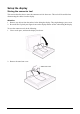
Setup the display Storing the connector tool This section describes how to store the connector tool for future use. This tool will be useful when disconnecting the cables from the display. Attention: 1. Remove any objects from the surface before tilting the display. They might damage your screen. 2. Be careful not to pinch your fingers between the display and the surface when tilting the display. To store the connector tool, do the following: 1. Clear a work space, and turn the display face down. 2.
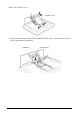
3. Remove the connector cover. Connector cover 4. Unhook the digital signal cable from the cable hook and lift it up to store the connector tool to the rear compartment of the display.
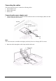
Connecting the cables This section describes how to connect the following cables: 1. Power adapter cord 2. Digital signal cable 3. Power cord Connecting the power adapter cord 1. Connect the power adapter cord to the DC-IN connector at the rear of the display. Make sure that it clicks firmly into the connector. Top view Video connector DC-IN connector bottom view Note: The video connectors A and B on the display are Safety Extra Low Voltage (SELV) circuits. 2.
3. Reinstall the connector cover on the display. Connector cover 4. Reinstall the stand rear cover and turn the display to the upright position. Stand rear cover Note: Do not power on the display or the computer until instructed. Failing to do so may damage these units or the video graphics card.
Connecting the digital signal cable 1. 2. 3. 4. Make sure that the video graphics card is installed on your computer. Make sure that the power cord is NOT connected to your computer. Open the cover of your computer, if necessary. Connect the connector end marked “1 PRIMARY” to the DVI port marked “1”, and the connector end marked “2 SECONDARY” to the DVI port marked “2” of the video graphics card. 2 SECONDARY connector USB connector 1 PRIMARY connector Video graphics card 5.
Connecting the power cord Note: Read the respective “Danger Statements” on pages 22 before continuing with this section. 1. Connect the power cord to the power adapter. 2. Connect the power plug to a properly grounded power outlet. Note: Make sure that all the cables are connected, otherwise the power-on light will not turn on. 3. Connect the computer to a properly grounded power outlet and turn on the power switch.
4. Press the power switch on the display. The power light comes on. Power switch Power light Notes: a. When you turn off the display, wait at least five seconds before turning it on again. b. If you accidentally disconnected the power cord from the main outlet and you connected it to the outlet again, the screen may flicker continuously. To stop the flicker, press the power switch and turn off the display, then turn it on again. c.
Adjusting and maintaining your display This chapter describes the following: • How to adjust the viewing angle. • How to set the controls. • The operating status of your display. • How to disconnect the cables. • How to use the security keylock. • How to maintain your display. Adjusting the viewing angle You can adjust the vertical angle of the display to avoid unnecessary light reflection and to make viewing easier.
Setting the display control buttons You can control the various functions of the display using the buttons at the front right of the display. The four buttons control the following functions: Button/Button Name Direct access functions Functions available from the OSD Menu Displays the on-screen display (OSD) Enters highlighted menu mode. menu. Menu/Enter Sets the screen to a dimmer view. Moves the cursor to the left for highlighting the icons or for making adjustments.
Accessing the on-screen display (OSD) menus You can access the on-screen display (OSD) menus by pressing the Menu/Enter button. The OSD menus enable you to set the various operating conditions of your display.
Submenus To access a submenu, do the following: Brightness submenu 1. Select the Brightness icon on the Main menu using the Left-Arrow or the Right-Arrow button. 2. Press the Menu/Enter button. The Brightness submenu appears. 3. Adjust the brightness using the Left-Arrow or the Right-Arrow button. 4. Press the Menu/Enter button to exit from this submenu. Video input submenu 1. Select the Video Input icon on the Main menu using the Left-Arrow or the Right-Arrow button. 2. Press the Menu/Enter button.
OSD Icon Description One video input mode. Two video input mode. (The color management function is always effective.) Four stripes video input mode. (The color management function is always effective.) Four tiles video input mode. (The color management function is always effective.) Exit from the Submenu. 1or 0 (to the left of the numbers) Sets the color management function or the smooth character display function.
Knowing the operating status of your display You can know the status of your display by the color of the power light. Power light The color of the power light changes from green to amber when your display receives a time-out video signal from the computer and enters Standby mode to save power. A time-out video signal is sent from your computer to the display when the former detects inactivity on the keyboard or mouse for a set duration of time.
Disconnecting the cable CAUTION: Do not use a digital signal cable other than the one shipped with the product. Using some other cable may damage the display or the video graphics card. The cable (P/N: 07N2227) is available at ViewSonic Customer Support Line (refer to page 21). Note: Before you begin the procedures below, be sure to read the “Danger Statements” on page 22. To disconnect the digital signal cable, do the following: 1.
Using the security keylock The display has a built-in security keyhole at the rear of the screen for fastening a security lock and cable. This lock is used to help prevent the display from being removed without your permission. This cable can be purchased at any PC shop. First secure the cable to a stationary object; then attach the lock to the keyhole on the rear of the display. For details of the installation, refer to the instructions shipped with the security keylock.
Troubleshooting Is something wrong? If you suspect that something is not working correctly, you should: 1. Turn on the computer and display. 2. Set the brightness control ( 3. 4. 5. 6. ) to the proper position. Make sure that all cables are securely connected. Disable the computer’s screen saver program, if it is enabled. Set the display mode to the supported display mode. If you still have a problem, go to the symptom list below and find the symptom that most resembles yours.
The screen is blank and the power indicator is blinking amber every second The display mode of the computer is outside the range of the display • Reconfigure the computer to use a supported display mode. • The video graphics card is defective. Replace it. • The computer is defective. Replace it. The screen is blank and the power indicator is blinking amber every 0.25 second The display fan is not working • Make sure that the power cord is firmly plugged into the electrical outlet.
Danger Statements DANGER To avoid shock hazard: • Do not remove the covers. • Do not operate this product unless the stand is attached. • Do not connect or disconnect this product during an electrical storm. • The power cord plug must be connected to a properly wired and grounded power outlet. • Any equipment to which this product will be attached must also be connected to properly wired and grounded power outlets.
DANGER Electric current from the power cords, telephone lines and communication cables is hazardous. To avoid shock hazard, connect and disconnect cables as shown below when installing, moving, or opening the covers of this product or attached devices. the power cord must be used with a properly grounded outlet. connect the power plugs to mains outlets located in the same panel. To Connect Turn everything OFF. To Disconnect Turn everything OFF. First remove the power cord from the outlet.
Notices Attention • Do not exert strong pressure to the surface of the display screen. You may break the LCD panel. • Do not place heavy objects on top of this product. They may damage the display. • Do not touch the display screen with your fingers. Fingerprints and oil stains may remain on the screen surface. They are difficult to wipe off. • The display is heavy. Ask the help of others if you cannot carry it by yourself.
License inquiries References in this publication to ViewSonic products, programs, or services do not imply that ViewSonic intends to make these available in all countries in which ViewSonic operates. Any reference to an ViewSonic product, program, or service is not intended to state or imply that only ViewSonic product, program, or service may be used.
Specifications The specifications of the display are as follows: Dimensions Width: Height: Depth: Depth (without stand): 547 mm (21.5 in.) 439 mm (17.3 in.) 196 mm (7.7 in.) 105 mm (4.1 in.) Weight Unpackaged: With base stand: 11.4 kg (25.1 lb.) Without base stand: 8.8 kg (19.4 lb.) Power adapter: 1.3 kg (2.9 lb.
Supported display modes The display supports the following display modes: DVI Input Horizontal Frequency (KHz) Vertical Frequency (Hz) Dot Clock Frequency (MHz) Actual Display Resolution 640 × 400 ch1 31.5 59.9 25.2 3200 × 2000 640 × 480 ch1 37.9 72.8 31.5 3200 × 2400 640 × 480 ch1 37.5 75.0 31.5 3200 × 2400 640 × 480 ch1 43.3 85.0 36.0 3200 × 2400 800 × 600 ch1 35.2 56.3 36.0 3200 × 2400 800 × 600 ch1 37.9 60.3 40.0 3200 × 2400 800 × 600 ch1 48.1 72.2 50.
Extended modes The addressability of the monitor is more advanced than those provided for in the industry standard display modes so in addition, monitor specific, or extended modes, have been developed. Detailed timing information on these modes is provided to the video graphics card and system through the VESA DDC/EDID protocol.
Updating the settings for your display Unless you change the video graphics card that drives your display, there is usually no need to change the settings. In case the need does arise, a procedure for changing them is given in this appendix. This operation must be done carefully. If incorrect parameters are specified, nothing will be displayed. Applicable models The procedure given in this document applies to displays with firmware at the following levels: DDC CPU Version 6.2 or higher OSD CPU Version 5.
2. Enabling the special OSD (on-screen display) menu a. Press a menu switch and either the left switch or the right switch to select the (i) (information) menu. On that menu, press the menu switch to enter the information menu. There, a display showing the refresh rate and the screen resolution appears, as in this example: b. Press the left switch three times, and then press the right switch three times.
If the setting is given as 000, any number greater than 63, or a value ending in X, an error has occurred; try step 3 on page 29 again. For details, see “Valid settings” on page 31. 4. Updating the settings a. From the table on page 31, choose the number of the settings you want to use. b. Set the brightness parameter to the value for the settings you have chosen (see “Brightness submenu” on page 15.).
Valid settings DDC-CPU version 6.2 can detect and update some settings. If it encounters any it does not recognize, it reads them as 000 (unknown). From the following table, choose the settings that are appropriate for the operating system and video graphics card you are using. If you want to use settings not listed in the table, consider upgrading to another version of DDCCPU. Settings are sometimes updated without notice. For the latest information, refer to http:// www.viewsonic.com.
Customer Support For technical support or product service, please contact ViewSonic. NOTE: You will need the product serial number. Country/Region Web site T = Telephone F = FAX Email United States viewsonic.com/support T: (800) 688-6688 F: (909) 468-1202 service.us@viewsonic.com Canada viewsonic.com/support T: (800) 688-6688 F: (909) 468-1202 service.ca@viewsonic.com Europe, Middle East, Baltic countries, and North Africa viewsoniceurope.com Contact your reseller service.eu@viewsoniceurope.
Compliance Compliance Information for U.S.A. This equipment has been tested and found to comply with the limits for a Class A digital device, pursuant to part 15 of the FCC Rules. These limits are designed to provide reasonable protection against harmful interference in a residential installation. This equipment generates, uses, and can radiate radio frequency energy, and if not installed and used in accordance with the instructions, may cause harmful interference to radio communications.
Geräte dürfen an Orten, für die sie nicht ausreichend entstört sind, nur mit besonderer Genehmigung des Bundesminesters für Post und Telekommunikation oder des Bundesamtes fur Post und Telekommunikation betrieben werden. Die Genehmigung wird erteilt, wenn keine elektromagnetischen Störungen zu erwarten sind. Hinweis: Dieses Genehmigungsverfahren ist von der Deutschen Bundespost noch nicht veröffentlicht worden.
Statements for Other Countries Power Cord For your safety, ViewSonic provides a power cord with a grounded attachment plug to use with this ViewSonic product. To avoid electrical shock, always use the power cord and plug with a properly grounded power outlet. Power cords used in the United States and Canada are listed by the Underwriter’s Laboratories (UL) and/or certified by the Canadian Standards Association (CSA).
Hinweise Gemäß der Amtsbltter des BMPT Nm. 61/1991 und 6/1992 wird der Betreiber darauf aufmerksam gemächt, daß die von ihm mit diesem Gerät zusammengestellte Anlage auch den technischen Bestimmungen dieser Amtsblätter genügen muß . Aus ergonomischen Gründen wird empfohlen, die Grundfarbe Blau nicht auf dunklem Untergrund zu verwenden (schlechte Erkennbarkeit, Augenbelastung bei zu geringem Zeichenkontrast).
LIMITED WARRANTY VIEWSONIC LCD DISPLAY What the warranty covers: ViewSonic® warrants its products to be free from defects in material and workmanship during the warranty period. If a product proves to be defective in material or workmanship during the warranty period, ViewSonic will at its sole option repair or replace the product with a like product. Replacement product or parts may include remanufactured or refurbished parts or components.
Appendix Power Cord Safety Guidelines Caution: Use a power cable that is properly grounded. Always use an AC power cord that meets your country’s safety standard. USA .............................. UL Canada......................... CSA Germany....................... VDE Switzerland ...................SEV Britain............................BASE/BS Japan ............................
Compliance Information for U.S.A. This equipment has been tested and found to comply with the limits for a Class B digital device, pursuant to part 15 of the FCC Rules. These limits are designed to provide reasonable protection against harmful interference in a residential installation. This equipment generates, uses, and can radiate radio frequency energy, and if not installed and used in accordance with the instructions, may cause harmful interference to radio communications.
ViewSonic Corporation