
Service manual


4. Circuit Description
Power Circuit:
Switching mode power supply provided 3 sets of Vcc power supply +5V, +12V and +24V. The
Details please refer to page 26 of schematic.
Vcc +5V : supply to Stand-By U48 chip and Main Board or Panel LVDS.
Vcc +12V : supply to Audio Processor, Audio Class-D AMP or Panel LVDS.
Vcc +24V : supply to Panel’s inverter.
A.
Cold-Opening Mode
Κ
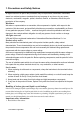
i.
Switching power will produce +5V when plug in and transmit to the Vsub pin of Stand-By U41 chip
via J17.
R318 0_NC
R319
0
J11
1
2
3
4
5
6
7
8
9
10
11
12
13
Vsub
V12IN
+5V Always on
ii. This machine is in Stand-By Mode now.
B.
Stand-By Mode(+5V)
Κ
i. When this machine is in Stand-By mode, only U41 SM5964C40J keep working, so the system can
assure the consumption power is < 1.0W in Stand-by Mode.
C. Power ON Mode(+5V ,+12V)
i. Receives the start order
When the system receives the start order by Power Key of the remote control ΰsignal mark IRupα
or Power ON/OFF of the control panelΰsignal mark PWSWα, it will process the following action.
R307 3.3K
C484
.01
U41 SM5964C40J
RST
10
XTAL2
20
XTAL1
21
GND
22
PSEN
32
ALE/PROG
33
EA/VPP
35
VCC
44
P1.0
2
P1.1
3
P1.2
4
P1.3
5
P1.4
6
P1.5
7
P1.6
8
P1.7
9
P2.0/A8
24
P2.1/A9
25
P2.2/A10
26
P2.3/A11
27
P2.4/A12
28
P2.5/A13
29
P2.6/A14
30
P2.7/A15
31
P3.0/RXD
11
P3.1/TXD
13
P3.2/INT0
14
P3.3/INT1
15
P3.4/T0
16
P3.5/T1
17
P3.6/WR
18
P3.7/RD
19
P0.0/AD0
43
P0.1/AD1
42
P0.2/AD2
41
P0.3/AD3
40
P0.4/AD4
39
P0.5/AD5
38
P0.6/AD6
37
P0.7/AD7
36
V5up
IRup
PWSW
R304
3.3K
V5up
ViewSonic Corporation Confidential - Do Not Copy N4261w-1M
7