® ViewSonic CD4220 LCD Commercial Display IMPORTANT: Please read this User Guide to obtain important information on installing and using your product in a safe manner, as well as registering your product for future service. Warranty information contained in this User Guide will describe your limited coverage from ViewSonic Corporation, which is also found on our web site at http:// www.viewsonic.
Content Safety Precautions..................................................................................................5 Package Contents...................................................................................................6 Parts Name and Functions.....................................................................................7 Control Panel............................................................................................................................ 7 Terminal Panel....
Compliance Information For U.S.A. This equipment has been tested and found to comply with the limits for a Class A digital device, pursuant to Part 15 of the FCC Rules. These limits are designed to provide reasonable protection against harmful interference when the equipment is operated in a commercial environment.
Important Safety Instructions 1. Read these instructions completely before using the equipment. 2. Keep these instructions in a safe place. 3. Heed all warnings. 4. Follow all instructions. 5. Do not use this equipment near water. Warning: To reduce the risk of fire or electric shock, do not expose this apparatus to rain or moisture. 6. Clean with a soft, dry cloth. If further cleaning is required, see “Cleaning the Display” in this guide for further instructions. 7. Do not block any ventilation openings.
Declaration of RoHS Compliance This product has been designed and manufactured in compliance with Directive 2002/ 95/EC of the European Parliament and the Council on restriction of the use of certain hazardous substances in electrical and electronic equipment (RoHS Directive) and is deemed to comply with the maximum concentration values issued by the European Technical Adaptation Committee (TAC) as shown below: Substance Proposed Maximum Concentration Actual Concentration Lead (Pb) 0.1% < 0.
Copyright Information Copyright © ViewSonic® Corporation, 2007. All rights reserved. Macintosh and Power Macintosh are registered trademarks of Apple Computer, Inc. Microsoft, Windows, Windows NT, and the Windows logo are registered trademarks of Microsoft Corporation in the United States and other countries. ViewSonic, the three birds logo, OnView, ViewMatch, and ViewMeter are registered trademarks of ViewSonic Corporation. VESA is a registered trademark of the Video Electronics Standards Association.
Safety Precautions FOR OPTIMUM PERFORMANCE, PLEASE NOTE THE FOLLOWING WHEN SETTING UP AND USING THE LCD COLOR MONITOR: y DO NOT REMOVE MONITOR BACK COVER. There are no user serviceable parts inside and opening or removing covers may expose you to dangerous shock hazards or other risks. Refer all servicing to qualified service personnel. y Do not spill any liquids into the cabinet or use your monitor near water.
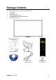
Package Contents Your new CD4220 monitor box* should contain the following: y LCD monitor y Power Cord y Video Signal Cable y User’s Manual in CD Wizard y Wireless Remote Control and AAA Batteries y Quick Start Guide (A4) LCD monitor Quick Start Guide Video Signal Cable CD Wizard Power cored For North America ViewSonic CD4220 Remote control & AAA batteries 6
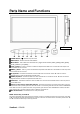
Parts Name and Functions Control Panel Button Location POWER button ( ) - Switches the power on/off. MUTE button - Switches the audio mute ON/OFF. INPUT button - Acts as SET button with OSD menu.(Toggle switches between [RGB1], [RGB2], [RGB3], [RGB4], [DVD/HD], [VIDEO] and [VIDEO] .) PLUS (+) button - Acts as (+) button to increase the adjustment with OSD menu. Increase the audio output level when the OSD menu is turned off.
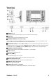
Terminal Panel AUDIO IN 1, 2, 3 To input audio signal from external equipment such as a computer, VCR or DVD player. AUDIO OUT To output the audio signal from the AUDIO IN 1,2 and 3 jack. EXTERNAL CONTROL (mini D-Sub 9 pin) Connect the IN connector with the RS-232C OUT connector of the computer or a multi-connected CD4220 monitor. Connect the OUT connector with the RS-232C IN connector of CD4220 monitor. VIDEO IN/OUT VIDEO IN connector (BNC and RCA): To input a composite video signal.
Wireless Remote Control LEFT button decrease Acts as (W) button to decrease the adjustment with OSD menu. Small screen which adjusted “PIP” mode moves left. ENTER button Acts as SET button with OSD menu. MENU button To switch the menu mode on/off. DISPLAY button To switch the information OSD on/off. INPUT button Selects from input signal, [RGB1], [RGB2], [RGB3], [DVD/HD], [VIDEO] and [VIDEO]. AUDIO INPUT button Press to change the audio source for each video source.
Operating Range for the Remote Control Point the top of the remote control toward the LCD monitor's remote sensor during button operation. Use the remote control within a distance of about 7 m/23 ft. from the front of the LCD monitor's remote control sensor and at a horizontal and vertical angle of within 30° within a distance of about 3 m/10 ft.
Setup Procedure 1. Determine the installation location CAUTION: DO NOT ATTEMPT TO INSTALL THE LCD MONITOR BY YOURSELF. Installing your LCD display must be done by a qualified technician. Contact your dealer for more information. CAUTION: MOVING OR INSTALLING THE LCD MONITOR MUST BE DONE BY TWO OR MORE PEOPLE.Failure to follow this caution may result in injury if the LCD monitor falls. CAUTION: Do not mount or operate the display upside down, face up, or face down.
7. Adjust the sound Make adjustments lowering or raising the volume as required. 8. Adjust the screen Make adjustments to the display position or settings if required. 9. Adjust the image Make adjustments to brightness or contrast if required. 10. Recommended Adjustment To reduce the risk of “image persistence”, please adjust the following items based on the application being used. “POWER SAVE”, “SCREEN SAVER”, “DATE AND TIME”, “SCHEDULE”. 11.
How to Mount and Attach Options to the LCD Monitor You can attach mounting accessories to the LCD monitor in one of the following two ways: 1. In the upright position 2. Lay the screen face down Protective Sheet Table Handles Tabletop Stand Lay the protective sheet on a table, which was wrapped around the monitor when it was packaged, beneath the screen surface so as not to scratch the screen face. This device cannot be used or installed without the Tabletop Stand or other mounting accessory.
4. To avoid monitor from falling Take measures to prevent the monitor from falling over in case of an earthquake or other disaster to lessen the probability of injury and damage resulting from fall. As shown in the figure, secure the monitor to a solid wall or pillar using rope (commercially available) strong enough to bear the weight of the monitor. (CD4220: approx. 30 kg) When you use screw hooks (commercially available), ring screw hooks, not C-shaped screw hooks (with opening), are recommended.
Connections Before making connections: 7 7 First turn off the power of all the attached equipment and make connections. Refer to the user manual included with each separate piece of equipment.
Connecting a Personal Computer Connecting your computer to your LCD monitor will enable you to display your computer's screen image. Some video cards may not display an image correctly. Connect the LCD Monitor to a Personal Computer y To connect the RGB 2 IN connector (mini D-sub 15 pin) on the LCD monitor, use the supplied PC - Video RGB signal cable (mini D-sub 15 pin to mini D-sub 15 pin). y When connecting one or more LCD monitors, use the RGB OUT connector (mini D-sub 15 pin).
Connecting with Digital Interface Equipment Connections can be made with equipment that is equipped with a digital interface compliant with the DVI (Digital Visual Interface) standard. Connect the LCD Monitor to a Computer with a Digital Output y The RGB 1, RGB 1 IN connector accepts a HDMI cable. y The RGB 1, RGB 1 IN connector can connect to HDMI output or DVI-D output of PC. y To maintain display quality, use a cable with a quality prescribed by DVI standards.
Connecting a DVD Player with component out Connecting your DVD player to your LCD monitor will enable you to display DVD video. Refer to your DVD player owner’s manual for more information. Connect the LCD Monitor to a DVD Player y To connect the DVD/HD In connector (BNC) on the LCD monitor, use a separately available BNC connector cable. You will need a BNC-to-RCA adapter to connect a DVD player with an RCA pin jack to the BNC connector cable (not provided).
Connecting to a Stereo Amplifier You can connect your stereo amplifier to your LCD monitor. Refer to your amplifier owner's manual for more information. Connect the LCD Monitor to a Stereo Amplifier y Turn on the LCD monitor and the amplifier only after all connections have been made. y Use an RCA cable to connect the AUDIO OUT connector (RCA) on the LCD monitor and the audio input on the amplifier. y Do not reverse the audio left and right jacks.
Basic Operation Power ON and OFF Modes The LCD monitor power indicator will turn green while powered on or red in off mode. The monitor can be powered on or off using the following three options: 1. Pressing the Main Power Switch. NOTE: When the Main Power Switch is used to power off the LCD monitor, the remote control and the power button will not activate the on mode and both green and red power indicator turn off. Be sure to turn the Main Power Switch to the on mode before using these two options. 2.
Power Indicator Power ON Power OFF Power Standby when “SCHEDULE” is enable Power Standby Diagnosis (Detecting failure) Status Green Red Red On Green Blinking Red, Green Red Blinking * See troubleshooting Using Power Management The LCD monitor follows the VESA approved DPM Power Management function. The power management function is an energy saving function that automatically reduces the power consumption of the display when the keyboard or the mouse has not been used for a fixed period.
Picture Mode RGB 1, 2 STANDARD CINEMA VIVID SOFT DVD/HD, VIDEO STANDARD CINEMA VIVID SOFT Audio Source Switching You can switch the audio source using the AUDIO INPUT button. RGB 1 HDMI AUDIO1 Other than RGB 1 AUDIO1 AUDIO2 AUDIO2 AUDIO3 AUDIO3 Control Lock Mode This function disables the operation buttons so that the adjustments you make are not changed when they are pressed. To disable the buttons, press and hold down the S and T buttons together for at least 3 seconds.
OSD (On-Screen-Display) Controls Remote Control Press MENU button to open Main menu. Press S or T button to select sub-menu. Press ENTER button to decide. Press S or T, and W or X button to select function, or control which you like. Press ENTER button to decide. Press MENU or EXIT button to exit. Control Panel Press EXIT button to open Main menu. Press S or T button to select. Press INPUT button to decide Press S or T, and ﹢ or – button to select function, or control which you like.
PICTURE BRIGHTNESS y Adjusts the image brightness in relation to the background. y Press + button to increase black level. y Press - button to decrease black level. CONTRAST y Adjusts the image brightness in relation to the input signal. y Press + button to increase contrast. y Press - button to decrease contrast. SHARPNESS y y y y This function is digitally capable to keep crisp image at any timings.
SCREEN H POSITION y Controls Horizontal Image position within the display area of the LCD. y Press + button to move screen to right. y Press - button to move screen to left. V POSITION y Controls Vertical Image position within the display area of the LCD. y Press + button to move screen to UP. y Press - button to move screen to DOWN. CLOCK * : INPUT RGB2 only y Press + button to expand the width of the image on the screen the right.
AUDIO BALANCE y y y y Adjust the balance of L/R volume. Press + button to move the stereo sound image to right. Sound of the left side will be small. Press - button to move the stereo sound image to left. TREBLE y To accentuate or reduce the high frequency sound. y Press + button to increase TREBLE sound. y Press - button to decrease TREBLE sound. BASS y To accentuate or reduce the low frequency sound. y Press + button to increase BASS sound. y Press - button to decrease BASS sound.
PIP (PICTURE IN PICTURE) Note: The “PIP” and “POP” modes do not function when the screen size is “CUSTOM” or “REAL”. PIP SIZE y Selecting the size of picture inserted at the “Picture-in-Picture” (PIP) mode. y “Large”, “Middle” and “Small” are available. PIP AUDIO y Selecting the sound source in PIP mode. y When selecting “MAIN AUDIO”, you will get the sound for the main picture and when selecting “PIP AUDIO”, you will get the sound for the picture instead.
CONFIGURATION 1 AUTO SETUP * : INPUT RGB2 only y Press "SET" button to automatically adjust screen size, horizontal position, vertical position, clock, clock phase, white level and black level. y Press "EXIT" button to cancel execution AUTO SETUP and then will return to the previous menu. AUTO ADJUST * : INPUT RGB2 only y Selecting the auto adjust ON/OFF. y Selecting ON when changing the timing, the horizontal position, vertical position and clock-phase will adjust automatically.
CONFIGURATION 2 OSD TURN OFF y The OSD control menu will stay on as long as it is use. In the OSD Turn Off submenu, you can select how long the monitor waits after the last touch of a button to shut off the OSD control menu. y The preset choices are 5 -120 seconds. INFORMATION OSD y Selects the information OSD display or not. y The information OSD will display when input signal or source change or warning message like as no-signal or out-of range. y A time between 1 to 10 seconds is available.
ADVANCED OPTION INPUT RESOLUTION * : INPUT RGB2 only y y y y y y Selects to decision of input signal about below timings, 1024x768, 1280x768 and 1360x768. AUTO: Determines the resolution automatically. 1024x768: Determines the resolution as 1024x768 1280x768: Determines the resolution as 1280x768 1360x768: Determines the resolution as 1360x768 The setting you select becomes effective when POWER is turned OFF and ON again.
TILING TILING demonstrates multiple screens. This feature provides a single large screen using up to 25 monitors. It will be able to divide up to 5 each H and V. This requires you to feed the PC output into each of the monitors through a distributor. H MONITORS: Select number of horizontal divide. V MONITORS: Select number of vertical divide. POSITION: Select a position to expand the screen.
For long life use of Public Display < Image Sticking of LCD Panel > When LCD panel is operated continuously for long hours, a trace of electric charge remains near the electrode inside LCD, and residual or “ghost” image of previous image may be observed. (Image Persistence) Image Persistence is not permanent, but when fixed image is displayed for long period, ionic impurities inside LCD are accumulated along the displayed image, and it is observed permanently.
< Remote control numbering function > By connecting multiple CD4220 monitors using RS-232C cables, you can control any one monitor or all the monitors by one remote controller. 1. Assign arbitrary ID number to each of multi-connected CD4220 monitors using MONITOR ID. ID numbers 1 to 26 are selectable. It is recommended to assign sequential ID numbers from 1 and up. 2. The remote control mode of the first CD4220 monitor is set to PRIMARY and those of the other monitors are set to SECONDARY. 3.
Controlling the LCD monitor via RS-232C Remote Control This LCD monitor can be controlled by connecting a personal computer with a RS-232C terminal. Functions that can be controlled by a personal computer are: Connection LCD Monitor + PC NOTE: We have two kinds of RS-232 protocol including serious connection and no serious connection that can use by user.
Appendix: Installing and removing stands How to install stands 1. Please turn monitor off. 2. After inserting stand in guide block, fasten Thumbscrews on both sides of the monitor. NOTE: Install the stands so that their longer portions come to the front. How to remove the stands 1. Spread the protective sheet on the fl at surface, such as a desk. 2. Place monitor on the protective sheet. 3. Remove screws with a screwdriver and place them in a safe place for reuse.
Features Reduced Footprint: Provides the ideal solution for environments requiring superior image quality but with size and weight limitations. The monitor’s small footprint and low weight allow it to be moved or transported easily from one location to another. Color Control Systems: Allows you to adjust the colors on your screen and customize the color accuracy of your monitor to a variety of standards.
Troubleshooting No picture • The signal cable should be completely connected to the display card/computer. • The display card should be completely seated in its slot. • Front Power Switch and computer power switch should be in the ON position. • Check to make sure that a supported mode has been selected on the display card or system being used. (Please consult display card or system manual to change graphics mode.
Specifications Product specifications LCD Module Frequency Diagonal: Pixel Pitch: Resolution: Color: Brightness: Contrast Ratio: Response time: View Angle: Design View Distance: Horizontal: Vertical: Pixel Clock Viewable Size Input Signal PC-Input: Video: Sync: Input-terminal: VIDEO Input: AUDIO Input: RS-232C: Output Signal PC-Output: In: Video: Sync: Output-terminal: VIDEO Output: AUDIO Output: Speaker Output: RS-232C: Out: Resolutions Supported Power Supply Power Consumption Operational Envir
Customer Support For technical support or product service, see the table below or contact your reseller. NOTE: You will need the product serial number. Country/Region Website T = Telephone F = FAX Email Australia/New Zealand www.viewsonic.com.au AUS= 1800 880 818 NZ= 0800 008 822 service@au.viewsonic.com Canada www.viewsonic.com T= 1-866-463-4775 F= 1-909-468-5814 service.ca@viewsonic.com Europe/Middle East/ Baltic countries/North Africa www.viewsoniceurope.
Limited Warranty VIEWSONIC® LCD DISPLAY What the warranty covers: ViewSonic warrants its products to be free from defects in material and workmanship, under normal use, during the warranty period. If a product proves to be defective in material or workmanship during the warranty period, ViewSonic will, at its sole option, repair or replace the product with a like product. Replacement product or parts may include remanufactured or refurbished parts or components.
Exclusion of damages: ViewSonic's liability is limited to the cost of repair or replacement of the product. ViewSonic shall not be liable for: 1. Damage to other property caused by any defects in the product, damages based upon inconvenience, loss of use of the product, loss of time, loss of profits, loss of business opportunity, loss of goodwill, interference with business relationships, or other commercial loss, even if advised of the possibility of such damages. 2.
Mexico Limited Warranty VIEWSONIC® DISPLAY PRODUCTS What the warranty covers: ViewSonic warrants its products to be free from defects in material and workmanship, under normal use, during the warranty period. If a product proves to be defective in material or workmanship during the warranty period, ViewSonic will, at its sole option, repair or replace the product with a like product. Replacement product or parts may include remanufactured or refurbished parts or components & accessories.
Contact Information for Sales & Authorized Service (Centro Autorizado de Servicio) within Mexico: Name, address, of manufacturer and importers: México, Av. de la Palma #8 Piso 2 Despacho 203, Corporativo Interpalmas, Col. San Fernando Huixquilucan, Estado de México Tel: (55) 3605-1099 http://www.viewsonic.com/la/soporte/index.htm NÚMERO GRATIS DE ASISTENCIA TÉCNICA PARA TODO MÉXICO: 001.866.823.2004 Hermosillo: Villahermosa: Distribuciones y Servicios Computacionales SA de CV.
CD4620/CD4220 RS232 protocol Table of Content 1 Introduction ....................................................................................................... 45 2 Description......................................................................................................... 45 2.1 Hardware specification ............................................................................................................45 2.2 Communication Setting...........................................................
3. Introduction This document describes the hardware interface spec and software protocols of RS232 interface communication between Viewsonic Commercial Display and PC or other control unit with RS232 protocol. Viewsonic CD4620 and CD4220 contain with 2 set of protocol command 1. Protocol 1, with ID This set protocol allow user to assign the ID in the command to control the specify ID monitor 2. Protocol 2, without ID The set protocol is best for single display control and for Viewsonic NMP-530.
5. Protocol 1 : with ID 5.1 Command Description Length: TV ID Command Type Command: Value[1~3]: CR Total Byte of Message excluding “CR” Identification for each of TV Identify command type, “s” (0x73h) : Set Command “g” (0x67h) : Get Command “r” (0x72h) : Reply Command “p” (0x70h) : RCU Pass-through “+” (0x2Bh) : Valid command Reply “-“ (0x2Dh) : Invalid command Reply Function command code: One byte ASCII code Three bytes ASCII that defines the value 0x0D 5.
Hex 0x38 0x30 0x32 0x73 ID 0x30 0x32 Command Type 0x2D 0x24 0x31 0x37 0x36 0x0D Value2 0x33 Value3 0x32 CR 0x0D Value3 0x35 CR 0x0D Value3 0x36 CR 0x0D Reply (Hex Format) Name Hex Length 0x34 CR 0x0D Example3: Set Tint as 32 for TV-03 and this command is valid Send (Hex Format) Name Hex Length 0x38 ID 0x30 0x33 Command Type 0x73 Command 0x27 ID 0x30 0x33 Command Type 0x2B CR 0x0D Value1 0x30 Reply (Hex Format) Name Hex Length 0x34 Example4: Set Tint as 75 for TV-03 and this c
OSD timeout Volume Mute 8 8 8 s s s 3 5 6 33 35 36 Off Timer 8 s 7 37 PIP Mode 8 s 9 39 PIP Sound select 8 s : 3A PIP position 8 s ; 3B PIP Input 8 s < 3C Monitor ID Key Pad 8 8 s s = A 3D 41 Remote Control 8 s B 42 Chinese 006 : Russian 005 ~120 Sec 000 ~ 100 000: OFF 001: ON (mute) 000: OFF 001~024 (hour) 000 : OFF 001: PIP 002: POP 003 : PBP 004 : PBPA 000: Main 001: PIP 000: Up 001: Down 002: Left 003: Right 000 : VGA 001 : HDMI1 002 : HDMI2 003 : AV 004 : YPbPr 0
5.3 Get-Function Listing The PC can interrogate the LCD Monitor for specific information. The Get-Function packet format consists of 5 bytes which is similar to the Set-Function packet structure. Note that the “Value” byte is always = 00.
Example3: Get Tint from TV-0007 and this command is valid. The Tint value is 32. Send (Hex Format) Name Hex Length 0x38 ID 0x30 0x37 Command Type 0x67 Command 0X65 Value1 0x30 Value2 0x30 Value3 0x30 CR 0x0D ID 0x30 0x37 Command Type 0x72 Command 0x65 Value1 0x30 Value2 0x33 Value3 0x32 CR 0x0D Reply (Hex Format) Name Hex Length 0x38 Example4: Get Tint from TV-07 , but the Brightness command ID is error and it is NOT in the command table.
6. Protocol 2 : without ID 6.1 Set function listing The PC can control the LCD Monitor for specific actions. The Set-Function command allows you to control the LCD monitor behavior in a remote sit through the RS232 port. The Set-Function packet format consists of 5 bytes. Note that the “Value” byte is always = 00.
Brightness Sharpness Color Tint Bass Treble Balance Picture Size 5 5 5 5 5 5 5 5 $ % & ‘ .
6.2 Get-Function Listing The PC can interrogate the LCD Monitor for specific information. The Get-Function packet format consists of 5 bytes which is similar to the Set-Function packet structure. Note that the “Value” byte is always = 00.
Get Function Length Get-Contrast Get-Brightness Get-Sharpness Get-Color Get-Tint Get-Volume Get-Mute Get-RCU Get-Key Pad Get-Input select Get-Power status Command Command Response Range Code Code (Hex) (Three ASCII bytes) (ASCII) a 61 000 ~ 100 b 62 000 ~ 100 c 63 000 ~ 100 d 64 000 ~ 100 e 65 000 ~ 100 f 66 000 ~ 100 g 67 000: OFF (unmuted) 001: ON (muted) h 68 000: Disable 001: Enable 002: Pass through i 69 000: Disable 001: Enable j 6A 000: VGA 001: HDMI1 002: HDMI2 003: AV 004: YPbPr 005: S-Video l
6.3 Remote Control Pass-through mode When PC sets the LCD monitor to Remote Control Pass through mode, the LCD shall send a three bytes packet (followed by “CR”) in response to RCU button activation. Note, that in this mode the RCU shall have no effect on the monitor function. For example: “+Volume” will not change the volume in the LCD but only sends “+Volume” code to PC over the RS232 port.