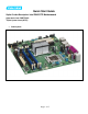
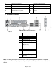
Quick Start Guide Viglen Product Description: Intel D945GTP Motherboard Viglen Order Code: PMPTPG01 Viglen System: Genie (S775) • Product photo Page 1 of 17
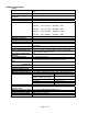
Product specification. Table 1.
Upgrading and ESD precautions WARNING Unplug the system before carrying out the procedures described in this document. Failure to disconnect power before you open the system can result in personal injury or equipment damage. Hazardous voltage, current, and energy levels are present in this product. Power switch terminals can have hazardous Voltages present even when the power switch is off.
STEPS TO TAKE TO PREVENT STATIC DISCHARGE: 1. The best way to prevent static discharge is to buy an anti-static strap from your local electrical shop. While you are wearing the strap and it is earthed, static charge will be harmlessly bled to ground. 2. Do not remove the component from its anti-static protective packaging until you are about to install it. 3. Hold boards by the edges - try not to touch components / interface strips etc.
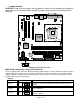
• System Board Components Figure 1 Motherboard Layout & Components Table 2. A B C Q R S Power connector (24 way ATX2.
J K L M N LGA775 processor socket Intel 82945G GMCH Processor fan connector DIMM Channel A sockets DIMM Channel B sockets Z AA BB CC DD O P SCSI LED connector (optional) I/O controller EE FF Front panel USB connectors Chassis intrusion connector Intel 82801G I/O Controller Hub (ICH7) SPI Flash device “Firmware Hub (FWH)” IEEE1394a controller not fitted optional IEEE1394a connectors not fitted optional Speaker • Back Panel Connectors Figure 2. Back Panel Connectors. Table 3.
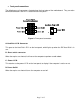
• Front panel connections The following are all connectors situated along the front edge of the motherboard. They are often connected to buttons and LED’s situated on the front panel. Figure 3. Front panel connectors A- Hard Disk L.E.D. Connector This goes to the Hard Disk L.E.D. on the front panel, which lights up when the IDE Hard Disk is in use. B - Reset switch connector When these pins are shorted, it will cause the computer to perform a cold reboot. C - Power L.E.D. This attaches to the power L.E.
• Motherboard Connectors There are connectors on the motherboard for FAN, IDE, Power supply, CD audio, Floppy, IDE, & Front Panel Connectors. The location and/or details of these connections are shown below. Figure 4.
• Jumper settings CAUTION Do not move any jumpers with the power on. Always turn off the power and unplug the power cord from the computer before changing a jumper setting. Otherwise, the board could be damaged. Figure 5. Motherboard jumper. BIOS Setup Configuration Jumper (J7J3) Settings The 3-pin jumper block determines the BIOS Setup program's mode. The table below describes the jumper settings for the three modes: normal, configure, and recovery.
System Memory The boards have four DIMM sockets and support the following memory features: • 1.8 V DDR2 SDRAM DIMMs with gold-plated contacts • Unbuffered, single-sided or double-sided DIMMs with the following restriction: Double-sided DIMMS with x16 organization are not supported. • 4 GB maximum total system memory total amount of addressable memory.
• Memory Configurations The Intel 82915G GMCH supports two types of memory organization: • Dual channel (Interleaved) mode. This mode offers the highest throughput for real world applications. Dual channel mode is enabled when the installed memory capacities of both DIMM channels are equal. Technology and device width can vary from one channel to the other but the installed memory capacity for each channel must be equal.
Dual Channel (Interleaved) Mode Configurations Figure 7 shows a dual channel configuration using two DIMMs. In this example, the DIMM0 (blue) sockets of both channels are populated with identical DIMMs. Figure 7. Dual Channel (Interleaved) Mode Configuration with Two DIMMs Figure 8 shows a dual channel configuration using three DIMMs. In this example, the combined capacity of the two DIMMs in Channel A equal the capacity of the single DIMM in the DIMM0 (blue) socket of Channel B. Figure 8.
Single Channel (Asymmetric) Mode Configurations NOTE Dual channel (Interleaved) mode configurations provide the highest memory throughput. Figure 10 shows a single channel configuration using one DIMM. In this example, only the DIMM0 (blue) socket of Channel A is populated. Channel B is not populated. Figure 10. Single Channel (Asymmetric) Mode Configuration with One DIMM Figure 11 shows a single channel configuration using three DIMMs.
Installing & Removing DDR2 SDRAM In-line Memory Modules (DIMMs) Installing Memory You can install from 128MB to 4GB of memory in the motherboard DIMM sockets. The board has four 240-pin DDR2 SDRAM DIMM sockets. The motherboard supports the following memory features: • • • 240-pin 1.8volt DIMMs with gold-plated contacts. Non-ECC (64-bit) or ECC (72-bit) memory. 128MB, 256MB, 512MB, 1GB and 2GB (in the future) modules.
Removing Memory To remove a DIMM, follow these steps: 1. 2. 3. 4. Observe the precautions in " Upgrading and ESD precautions”. Turn off all peripheral devices connected to the computer. Turn off the computer. Remove the computer cover. Gently spread the retaining clips at each end of the socket. The DIMM pops out of the socket. Hold the DIMM by the edges, lift it away from the socket, and store it in an antistatic package. 5.
BIOS Initial Release. NT94510J.86A.1348 Drivers initial release Windows 98SE, Windows ME, Windows NT4 Drivers are all not supported Windows 2000 Drivers Audio: Sigmatel 9220/9221 5.10.4455.0 4.16 MB 10 May 2005 INF: Intel® Chipset Software Installation Utility 7.0.0.1025 789 KB 27 May 2005 LAN: Intel® PRO Network Connections 10.0 15.7 MB 3 May 2005 Video: Intel® Graphics Media Accelerator 6.14.10.4332 4,491 MB Driver 16 June 2005 Windows XP Drivers Audio: Sigmatel 9220/9221 5.10.4487.0 14.