
Installation Guide


3
Your new faucet is designed for years of trouble-free performance.
Keep it looking new by cleaning it periodically with a soft cloth. Avoid abrasive
cleaners, steel wool and harsh chemicals as these will scratch, dull, and/or
damage the finish and void the warranty.
MAINTENANCE
ASSEMBLY
REQUIRED TOOLS
Adjustable wrench
Allen key - supplied (to remove cartridge if needed)
Plumber's putty - optional
Pipe tape
Flat screwdrivers
SAFETY TIPS
If you use soldering for the installation of the faucet, the seats, cartridges and
washers will have to be removed before using flame. Damage caused by
improper soldering will void the warranty.
Protect your eyes with safety glasses when cutting or soldering water supply
lines.
IMPORTANT POINTS
Prior to beginning installation, turn off the cold and hot water lines and open the
hot and cold knobs on the old faucet to release pressure.
When installing your new faucet, turn the connector nuts finger-tight, then use
one wrench to anchor the fitting and a second wrench to tighten the nut.
Connections that are too tight will reduce the integrity of the system and
potentially cause product failure which could lead to water damage.
Wrap all threaded connections with pipe tape available at your local hardware or
plumbing supply store. Always wrap in a clockwise direction.
Not all necessary supplies to install your faucet are included, however, they are
available wherever plumbing supplies are sold.
Prior to installing the faucet please FLUSH THE HOT AND COLD WATER
SUPPLY LINES that are or will be connected to the new faucet to remove scale,
solder or their impurities which could damage the faucet and potentially void the
warranty.
INSTALLATION
Installation must be done by a qualified licensed plumber.
Prior to installation please read the instructions thoroughly, confirm that all parts
are included and visually inspect the unit for any defects.
If you have any questions please contact the Vigo Technical Support
Department before proceeding with installation.
3
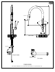
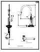
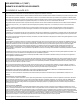
PLASTIC HOLDER
ALLEN KEY (REMOVES HANDLE
TO ACCESS CARTRIDGE)
TWO METAL
BRAIDED HOSES
NUT
COUNTERWEIGHT
SPRAYER
METAL RING
RUBBER RING
6
2
1
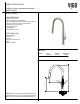
FAUCET
ASSEMBLY
PACKAGE CONTENTS
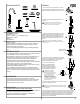
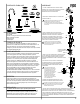
1. SHUT OFF WATER SUPPLY. REMOVE THE OLD FAUCET
AND FLEXIBLE HOSES. CLEAN SINK SURFACE WITH A NON
ABRASIVE CLEANER IN PREPARATION FOR THE NEW FAUCET.
ENSURE THAT YOU USE PIPE TAPE AND DO NOT OVER
TIGHTEN THE SUPPLY LINE NUTS AS THIS COULD CAUSE
PRODUCT FAILURE LEADING TO WATER DAMAGE.
!
2. THREAD FEMALE END OF METAL BRAIDED HOSE TO THE
FAUCET (2).
7. AFTER INSTALLATION IS COMPLETE, TURN ON THE WATER SUPPLY AND ALLOW BOTH
HOT AND COLD WATER TO RUN SEPARATELY FOR AT LEAST TWO MINUTE EACH. WHILE
WATER IS RUNNING, CHECK FOR LEAKS. IT IS IMPORTANT TO VIEW THE CONNECTIONS
AT THE MALE AND FEMALE FLEXIBLE HOSE CONNECTIONS. IF LEAKS ARE DETECTED,
REFER BACK TO THE INSTRUCTIONS AND ADJUST ACCORDINGLY. TIGHTENING NUTS
SLIGHTLY MAY STOP ANY MINOR LEAKS.
6. ATTACH THE FEMALE CONNECTIONS OF THE FLEXIBLE HOSES TO
THE COLD AND HOT WATER SUPPLY .
5. (IF NOT DONE ALREADY) ATTACH
SPRAYER TO FEMALE CONNECTION
OF SPRAYER HOSE BY HAND AND
TIGHTEN UNTIL SECURE. MAKE SURE
THE BLACK WASHER WITH SCREEN IS
SEATED AND INSTALLED PROPERLY.
!
ENSURE THAT PARTS ARE ASSEMBLED IN THE ORDER AS
DEPICTED IN DIAGRAM TO PREVENT DAMAGE TO FAUCET AND
SUPPLY LINES.
3. POSITION THE FAUCET IN THE COUNTERTOP HOLE, FROM
BENEATH THE COUNTERTOP HOLE ASSEMBLE THE PLASTIC
HOLDER, RUBBER RING, AND METAL RING IN THE ORDER
DEPICTED IN THE DIAGRAM. THEN THREAD METAL NUT ONTO
HOLLOW PIN. TIGHTEN THE METAL NUT UNTIL FAUCET IS
SECURE.
4. ATTACH SPRAY HOSE TO THE COPPER PIN (THE LONGEST
PIN). PUSH IN THE TAB AND SLIDE THE SPRAY HOSE INTO THE
COPPER PIN. IT WILL MAGNETICALLY ATTACH. ATTACH
SUPPLIED COUNTERWEIGHT TO THE HOSE.
NUT
STABILIZES FAUCET
UNDER COUNTERTOP
!
ENSURE THAT YOU USE PIPE TAPE AND ADJUSTABLE WRENCH, DO NOT
OVER TIGHTEN AS THIS COULD CAUSE PRODUCT FAILURE LEADING TO
WATER DAMAGE.
!
USE WASHER WITH SCREEN AT
CONNECTION POINT BETWEEN
SPRAYER AND SPRAYER HOSE. THIS
WILL STOP DEBRIS FROM TRAVELING
INTO THE SPRAYER HEAD AND
EFFECTING ITS FUNCTIONALITY.
PLEASE NOTE THAT THE SCREEN
WASHER WILL NEED TO BE REMOVED
AND CLEANED APPROXIMATELY ONCE
EVERY 3 MONTHS TO AVOID BUILD UP
AND LOW WATER FLOW.
4
TAB