VIGO INDUSTRIES INSTALLATION GUIDE FOR SHOWER AND TUB DOOR (MODEL VG06043) ! SAFETY PRECAUTIONS This Installation Guide uses the following symbols to indicate important information. Always observe the instructions indicated by these symbols. ! WARNING Instructions that, if ignored, could result in death or serious personal injury caused by incorrect handling or installation of the product. These instructions must be observed for safe installation.
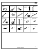
MODEL VG06043 LUCA INSTALLATION INSTRUCTIONS FOR SHOWER AND TUB DOOR PLEASE READ INSTRUCTIONS BEFORE PROCEEDING Parts List 1. 2. 3. 4. 5. 6. 7. 8. 9. Wall mount bracket (2pc) Fixed panel holders (1pc) Rollers (2pc) Fixed panel (1pc) Door (1pc) Handle assembly (1pc) Bottom door guide (1 pc) Door threshold (1pc) Vertical rail seal strip (1pc) (pre-installed on glass) 10. 11. 12. 13. 14. 15. 16. 17. 18. 19. 20.
1. WALL MOUNT BRACKET ASSEMBLY 2. FIXED PANEL HOLDER 98088 98078 4. FIXED PANEL WITH WALL SIDE SEAL STRIP 3. ROLLERS 5. DOOR 97033-60x74 98089 97032-60x74 PLATE 6. HANDLE ASSEMBLY 7. BOTTOM DOOR GUIDE 98023 98090 8. DOOR THRESHOLD 9. VERTICAL RAIL SEAL STRIP 95005-60 96023 11. DOOR AND FIXED PANEL SEAL STRIP 12. DOOR SEAL STRIP 10. STRUCTURAL RAIL 13. VERTICAL RAIL 98091-60 14. THRESHOLD EXTENSION CLIP 15. PLASTIC ANCHOR GREEN 98092 96024 96025 16.
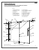
C B A MODEL DIMENSION "A" (DOOR) DIMENSION "B" (FIXED PANEL) VG06043XX6074 32 1/8" x 78 1/8" 28 1/4" x 78 3/4" VG06043XX6058 32 1/8" x 57 3/8" 28 1/4" x 57 13/16" ADJUSTABLE DIMENSION "C" (WIDTH) HEIGHT DOOR OPENING WIDTH 56"-60" 78 3/4" 27 3/16" 56"-60" 57 13/16" 27 3/16" A, B & C DIMENSIONS WERE MEASURED AFTER SHOWER ENCLOSURE WAS COMPLETELY INSTALLED Product lines may change, contact your Vigo representative at 1-866-591-7792 or visit our website at www.vigoindustries.
! WARNING VIGO STRONGLY RECOMMENDS THIS INSTALLATION BE COMPLETED BY A LICENSED PROFESSIONAL. INSTALLATION OF DOOR UNIT REQUIRES AT LEAST TWO PEOPLE. INSTALLATION OF THE SHOWER DOORS BY AN INEXPERIENCED PERSON MAY RESULT IN GLASS BREAKAGE AND CONSEQUENTLY, CAUSE PERSONAL INJURY OR DEATH. - Handle fragile items with care to prevent personal injury or material damage. - The glass panels are tempered and cannot be cut. Never attempt to do so.
IMPORTANT Verify that the overall size of the shower door opening is appropriate for the shower enclosure. Due to individual site variations, exact guidelines for every situation cannot be supplied. The recommended framing and dimensional requirements are shown for a typical application and may vary depending on the site requirements. To prevent damage to the finish, you should protect the shower cabin bottom with a cardboard protector before beginning the installation.
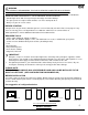
2. Position the vertical rail against the wall, making sure the bottom rests on the floor or base or tub for tub model. Use a level to be sure the rail is straight. Mark holes on the wall for the 4 mounting screws. A2 13 3. Remove the vertical rail and drill holes. Place plastic anchors (#15) inside them.
4. Replace the vertical rail and screw it into the plastic anchors with the phillips screws (#17). ! Preferred method of installation negates anchors and has the installation going right into the studs. There is a 5mm adjustment on the vertical rail (based off the depth of the track) for any minor adjustments. A4 15 13 17 5. Place the fixed panel with the pre-installed vertical seal strip into the vertical rail.
B. INSTALLING THE STRUCTURAL RAIL 1. Place the wall mount brackets (#1) on both ends of the structural rail and lightly tighten for dry fit purposes. Place rail into the cabin opening. If the rail is too long, cut it with a hacksaw to fit the opening. ! Make sure to cut the rail on the door side only. B1 10 1 13 2. Remove the fixed panel holder cover. Place the fixed panel holder through the hole in the fixed panel, replace the cover and tighten.
3. Position the fixed panel (#4) and the structural rail assembly (#10) correctly using a level. Mark the location of the wall mount brackets on the wall. B3 10 1 13 4 4. Remove the rail from the dry fit and remove the wall mount brackets from the structural rail. B4 1 10 5. Line the outside of the wall mount brackets with the markings on the wall. With the plates still installed to the wall mount brackets mark the wall at the center portion of the plate.
Untighten the plates from the wall mount brackets and center the plates to the wall markings. When installing, the center dimension of the wall mount bracket plate to the curb is *76 1/2" for the shower door model and *55 3/4" for the tub door model and the center dimension of the wall mount bracket plate to the center of the vertical rail is 7/8". *NOTE: The measurements of 55 3/4", 76 1/2" and 7/8" should just be used as a guide. Your actual dimension may vary. B6 7/8" PLATE *55 3/4" or *76 1/2" 6.
8. Slide the bracket body in position on the structural rail. Align the plates to the rail and slide the bracket body over the plate. Lock the bracket body to the plate with the supplied allen key (note the screws should be at the top of the rail). Make sure the structural rail is level. If the rail is not level then loosen the bracket body, slide out of the way and adjust the plate as needed. There is a 5mm adjustment built in. B8 PLATE 10 HEX SCREW (ON TOP) BRACKET BODY 1 PLATE PLATE 5mm 10 9.
C. INSTALLING THE DOOR 1. Remove the rollers (#3) from the box, note that these are fully installed. Carefully unthread the cap with a small head allen key. You will see a big hex screw, this is referred to as the roller height adjustment screw. SMALL HEX HOLE ROLLER (3) C1 3/8" VARIANCE ROLLER HEIGHT ADJUSTMENT SCREW ROLLER (3) SMALL HEX HOLE ROLLER HEIGHT ADJUSTMENT SCREW 2. Use the provided allen key to unscrew the adjustment screw and dismantle the roller.
4. 5. Place the two top rollers and the door panel (#5) assembly onto the structural rail (#10). Note that the rollers have a built-in mechanism that will provide adjustment for walls that are not 100% perpendicular to the floor. If necessary, loosen the adjustment screw and rotate the individual roller. This will raise or lower the height that the roller sits on the structural rail. Please refer to pages 20-21 for Roller Adjustments to Accommodate Out of Square Openings .
6. Screw the two bottom roller guides (#20) to the door panel (#5) using the allen key supplied. C6 20 INSIDE OF THE SHOWER SMALL HEX HOLE 5 D. INSTALLING THE THRESHOLD IMPORTANT IN CASE THE THRESHOLD IS CUT TOO SHORT, USE THE THRESHOLD EXTENSION CLIP (#14) TO EXTEND THE THRESHOLD ACCORDINGLY. 1. D1 Place the threshold (#8) into the bottom door guide (#7). Note that the end of the threshold should go halfway inside the bottom door guide.
2. Remove the threshold. Apply silicone to the underside of the threshold. Place the threshold back into its shower base location. Align the threshold and press firmly down. Apply silicone to the threshold around the inside and outside of the shower base. Remove any excess silicone from the threshold. D2 8 E. INSTALLING THE HANDLE 1. Unscrew the handle holders from the handle assembly (#6). E1 6 2. E2 Place the handle to the position on the door.
3. Tighten the handle nuts from inside the shower. E3 5 6 F. INSTALLING THE WATER SEAL STRIP 1. Attach the seal strip (#12) to the fixed panel. Start at the bottom and work your way up, using the heel of your hand to firmly press the seal strip onto the glass.
2. Trim the flange on the seal strip so that there is enough clearance for the door to roll without the seal strip hitting against the rollers. F2 4 5 Trim the flange of the seal strip (#12) to below this point 12 Flange 12 G. APPLYING THE SILICONE 1. Apply clear silicone caulking along the wall and floor of the shower enclosure interior. Apply clear silicone caulking along the fixed panel and threshold of the shower enclosure interior.
! IMPORTANT - WAIT 24 HOURS BEFORE USING SHOWER - DO NOT ALLOW WATER TO DIRECTLY HIT DOOR SEAL STRIPS. CLEANING INSTRUCTIONS FOR THE SHOWER CABIN AND DOOR PANEL 1. Use a mild liquid household cleaner to keep metal surfaces bright and clean. Rinse well and dry with a soft, clean cloth. 2. Remove dust with a soft, damp cloth. 3. Use a standard household window cleaner to clean the glass panels. 4.
IMPORTANT ROLLER ADJUSTMENTS TO ACCOMMODATE OUT OF SQUARE OPENINGS NOTE: There is a 3mm adjustment in the roller to use in the case that your walls are not plumb and level. Using an allen key, you will be able to adjust the roller to accommodate for the variance. 1. 2. 3. 4. 5. Loosen the hex screw to allow for movement. Then place the allen key in the small hex hole as shown and roll it to the right or left to make the adjustment. [See Fig.1] Fig.1A displays the 3 different positions.
The small hex hole on the roller will be facing up on this roller. The small hex hole on the roller will be facing up, on this roller. ROLLER (3) ROLLER (3) A B WALL WALL STRAIGHT WALLS WALL DIRECTION STRAIGHT WALL ROLLER "A" SMALL HEX HOLE DIRECTION ROLLER "B" SMALL HEX HOLE DIRECTION UP FIG. 2 The small hex hole on the roller will be facing up on this roller. The small hex hole on this roller will be adjusted to meet the gap.
SHOWER ENCLOSURE LIMITED LIFETIME WARRANTY EFFECTIVE JANUARY 1, 2010 owner or end-user for personal household use. For commercial uses, additional limitations apply.