VIGO INDUSTRIES INSTALLATION GUIDE FOR SHOWER ENCLOSURE (MODEL VG06045) ! SAFETY PRECAUTIONS This Installation Guide uses the following symbols to indicate important information. Always observe the instructions indicated by these symbols. ! WARNING Instructions that, if ignored, could result in death or serious personal injury caused by incorrect handling or installation of the product. These instructions must be observed for safe installation.
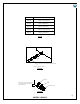
INSTALLATION INSTRUCTIONS FOR STANDING SHOWER CABIN Packing List 1. Top Wall Mount Bracket Assembly (2pc) 1A. Bottom Wall Mount Bracket Assembly (2pc) 2. Top Roller Guide (1pc) 3. Rollers (2pc) 4. Fixed Panel (1pc) 5. Door Panel (1pc) 6. Handle Assembly (1pc) 7. Fixed Panel Holder (1pc) 8. Top Structural Rail (1pc) 9. Bottom Structural Rail (1pc) 10. Door and Fixed Panel seal strip (2pc) 11. Door Bottom Seal Strip (1pc + 1 extra) 12. Glass Supports (2pc) 13. Hex Screw 1 5/8" (6pc) 14.
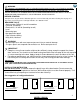
1. TOP WALL MOUNT BRACKET ASSEMBLY 98078 5. DOOR 2. TOP ROLLER GUIDE 6. HANDLE ASSEMBLY 7. FIXED PANEL HOLDER 97031-48 97031-50 97031-60 97031-62 97031-64 10. DOOR AND FIXED PANEL SEAL STRIP 11. DOOR BOTTOM SEAL STRIP-3 pack 96001 17. HEX SCREW COVER 8. TOP STRUCTURAL RAIL 9. BOTTOM STRUCTURAL RAIL 98083-48 98083-50 98083-60 98083-62 98083-64 98082 12. GLASS SUPPORTS 13. HEX SCREW 1 5/8" 98039 98084-48 98084-50 98084-60 98084-62 98084-64 14. PHILLIPS SCREW 3/4" 98033 98085 96021 15.
! WARNING WE STRONGLY RECOMMEND THAT A LICENSED PROFESSIONAL INSTALL THIS STANDING SHOWER CABIN AND INCLUDE THE ASSISTANCE OF A SECOND PERSON TO INSTALL THE DOOR UNIT. INSTALLATION OF THE SHOWER DOORS BY AN INEXPERIENCED PERSON MAY RESULT IN GLASS BREAKAGE AND CONSEQUENTLY, CAUSE PERSONAL INJURY OR DEATH. BEFORE STARTING Compare items on your invoice with what you have received. Carefully review the Packing List on page 2. If any items are missing, please call Vigo Industries at 1-866-591-7792.
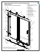
IMPORTANT Verify that the overall size of the shower door opening is appropriate for the shower enclosure. Due to individual site variations, exact guidelines for every situation cannot be supplied. The recommended framing and dimensional requirements are shown for a typical application and may vary depending on the site requirements. To prevent damage to the finish, you should protect the shower cabin bottom with a cardboard protector before beginning the installation.
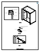
MODEL DIMENSION TO FINISHED WALL 48X74 22 3/4" (577.5mm) 50X74 23 3/4" (603mm) 60X74 28 3/4" (730mm) 62X74 29 3/4" (755.5mm) 64X74 30 3/4" (781mm) FIG.2 9 FIXED PANEL HOLDER ARROW MARKER VIEW FROM THE INSIDE FIG.2A HOUSING 1A SCREW COUNTER CLOCKWISE TO LOOSEN FOR ACCESS TO MOUNTING CLIP MOUNTING CLIP FIG.
4 4 LEVEL 1 1 9 7 7 9 FIG.2C 4 HEX SCREWS 1 9 9 1 7 7 VIEW FROM THE INSIDE VIEW FROM THE OUTSIDE FIG.
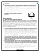
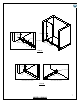
B. 1. 2. 3. 4. 5. 6. 7. 8. 9. INSTALLING THE FRONT FIXED PANEL Remove the fixed panel holder face plate/cap from the inside facing portion of the fixed panel holder (#7). Arrange glass to the preferred configuration. [SEE FIG.1A on page 4] This needs to match the location of the fixed panel holder (#7) from step "A". Install the seal strip (#10) to the wall side of the front fixed panel (#4). [SEE FIG.
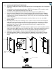
HEX SCREW (13) WALL INSIDE OF SHOWER OUTSIDE OF SHOWER HEX SCREW FIXED PANEL (4) GLASS SUPPORT (12) GASKET VIEW FROM THE TOP FIG.4 4 FIXED PANEL (4) 4 CAP 7 7 FIXED PANEL HOLDER (7) VIEW FROM THE OUTSIDE GASKET VIEW FROM THE SIDE 14 FIXED PANEL (4) FIXED PANEL HOLDER (7) HEX SCREW 15 VIEW FROM THE INSIDE FIG.5 C. 1. 2. 3. 4. 5. 6. INSTALLING THE TOP STRUCTURAL RAIL The top roller guide (#2) is already placed on the top structural rail (#8) for your convenience.
1 8 8 TOP ROLLER GUIDE (2) LEVEL OUTSIDE OF SHOWER INSIDE OF SHOWER 2 4 FIXED PANEL (4) FIG.6 SCREW COUNTER CLOCKWISE TO LOOSEN FOR ACCESS TO MOUNTING CLIP 1 HOUSING MOUNTING CLIP FIG.6A 8 1 4 2 COMPLETED FIG.
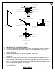
D. 1. 2. 3. 4. 5. 6. 7. INSTALLING THE DOOR Remove the rollers (#3) from the box. Remove the cover. The three outside screws is what you will loosen to place the rollers on the door. The center screw is referred to as the roller height adjustment screw. Install the door bottom seal strips (#11) onto the bottom of the door panel. [SEE FIG.8] Loosen the screws and dismantle the roller. Place the roller in the space in the glass at the bottom of the door panel (#5).
WALL SIDE 5 10 FIG.9 8 TOP ROLLER GUIDE (2) HEX SCREWS OUTSIDE OF SHOWER INSIDE OF SHOWER FIXED PANEL (4) DOOR PANEL (5) FIG.
E. 1. INSTALLING THE WATER SEAL STRIP Place the door seal strip (#19) to the door and to the fixed panel, respectively. [SEE FIG.11] 19 4 This end must look inside the shower 5 19 FIG. 11 F. 1. 2. INSTALLING THE HANDLE Unscrew the handle holders from the handle assembly (#6). Install the handle as shown. Make sure to have gaskets between any metal and glass. [SEE FIG.
G. APPLYING THE SILICONE 1. 2. Apply clear silicone caulking to the inside between the wall and side seal strip. [SEE FIG.13]. Apply clear silicone caulking to the inside between the floor and the fixed front panel. FIG.13 H. 1. 2. INSTALLING COVERS Install screw covers (#17) to the unit. Install roller covers. There is no need to install silicone between the roller cover and the roller. Applying silicone here will not allow for future height modification.
IMPORTANT ROLLER ADJUSTMENTS TO ACCOMMODATE OUT OF SQUARE OPENINGS NOTE: There is an adjustment on the roller to accommodate walls that are not 100% plumb. The bottom screw on the face of the roller adjusts the height of the ball bearing inside. Loosen this screw, adjust to desired closed door position and tighten in place. You may need to remove door unit from install to modify height. 1. 2. 3. 4. 5. Loosen the roller height adjustment screw to allow for movement. [See Fig.1] Fig.
WALL WALL A The roller height adjustment screw is in the normal position B The roller height adjustment screw is in the normal position STRAIGHT WALLS WALL DIRECTION ROLLER "A" ROLLER HEIGHT ADJUSTMENT SCREW ROLLER "B" ROLLER HEIGHT ADJUSTMENT SCREW STRAIGHT WALL NORMAL NORMAL FIG.
TILTS IN AT TOP (EXAGGERATED FOR PURPOSE OF DEPICTION) WALL OUT OF PLUMB WALL A The roller height adjustment screw is in the lowest position B The roller height adjustment screw is in the highest position TOP ANGLED WALL WALL DIRECTION TOP ANGLED ROLLER "A" ROLLER HEIGHT ADJUSTMENT SCREW ROLLER "B" ROLLER HEIGHT ADJUSTMENT SCREW LOWEST HIGHEST FIG.
WALL OUT OF PLUMB WALL A The roller height adjustment screw is in the highest position B TILTS IN AT BOTTOM (EXAGGERATED FOR PURPOSE OF DEPICTION) The roller height adjustment screw is in the lowest position BOTTOM ANGLED WALL WALL DIRECTION ROLLER "A" ROLLER HEIGHT ADJUSTMENT SCREW ROLLER "B" ROLLER HEIGHT ADJUSTMENT SCREW BOTTOM ANGLED HIGHEST LOWEST FIG.
VG06045 RIGHT DOOR OPENING VG06045 LEFT DOOR OPENING 19 MODEL VG06045
! IMPORTANT - WAIT 24 HOURS BEFORE USING SHOWER - DO NOT ALLOW WATER TO DIRECTLY HIT DOOR SEAL STRIPS. CLEANING INSTRUCTIONS FOR THE SHOWER CABIN AND DOOR PANEL A. B. C. D. Use mild liquid household cleaners to keep metal surface bright and clean. Rinse well and dry with a clean cloth. Remove dust with a soft, damp cloth. Use rubbing alcohol to clean and remove grease, oil, paint, and ink. Accidental scratches or stains will rarely show.
SHOWER ENCLOSURE LIMITED LIFETIME WARRANTY EFFECTIVE JANUARY 1, 2010 only to the original owner or end-user for personal household use. For commercial uses, additional limitations apply.