
Use and Care Manual


MODEL VG06064
15
E1
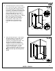
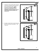
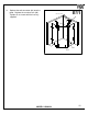
E. INSTALLING THE SUPPORT ASSEMBLIES
1. Install the wall connector (#9) and the
structural arm (#6) into the support
assembly (#21) that is already attached
to the side glass panel (#10). Make
sure it's level. Mark the position of the
wall connector (#9) on the wall.
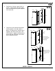
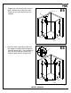
2. Remove the structural arm (#6).
Line
the outside of the wall connector (#9)
with the markings on the wall. With the
plate still installed to the wall connector,
mark the wall at the center portion of the
plate. Note: There is a 6mm
adjustment built into the mounting
plate of the wall connector (#9). It is
important to perform a dry fit prior to
install. Once everything is level and
plumb then you can begin your
drilling.
10
21
14
16
LEVEL
9
MARK HERE
E2
10
9
MARK THE WALL AT
THE CENTER
PORTION OF THE
PLATE WITH A
PENCIL
!
6
6mm