BSS Configuration and User Guide 2.4.
BSS C O NFI GUR ATI ON AND U SER G UIDE Copyright © VNL® 2010-2011 – All Rights Reserved Disclaimer No part of this document may be reproduced in any form without the written permission of the copyright owner. The contents of this document are subject to revision without notice due to continued progress in methodology, design, and manufacturing. VNL® shall have no liability for any error or damage of any kind resulting from the use of this document.
BSS C O NFI GUR ATI ON AND U SER G UIDE Contents 1. About This Document ....................................................... 10 1.1 Purpose ............................................................................ 10 1.2 Intended Audience ........................................................... 10 1.3 Document Conventions .................................................... 10 1.4 Terms and Abbreviations ................................................. 11 1.5 References ....................
BSS C O NFI GUR ATI ON AND U SER G UIDE 3.3 Configuring Trunkport....................................................... 26 3.3.1 Viewing Trunkport Details .......................................... 26 3.3.2 Locking/Unlocking Trunk ............................................ 28 3.3.3 Activating Trunkport ................................................... 29 3.3.4 Deactivating Trunkport ............................................... 30 3.4 Configuring MLPPP .........................................
BSS C O NFI GUR ATI ON AND U SER G UIDE 5.2.3 Deleting LinkSet ......................................................... 62 5.2.4 Deleting SS7 Route .................................................... 62 5.2.5 Deleting Link ............................................................... 63 5.2.6 Deleting A-Interface.................................................... 63 6. Radio Network Configuration .......................................... 64 6.1 Configuring ARFCN ................................
BSS C O NFI GUR ATI ON AND U SER G UIDE 6.4.10 Deleting Cell ........................................................... 100 6.5 Configuring BTS ............................................................. 100 6.5.1 Adding BTS .............................................................. 101 6.5.2 Setting Administrative State of BTS ......................... 102 6.5.3 Viewing BTS Configuration Data.............................. 103 6.5.4 Adding TRX ..................................................
BSS C O NFI GUR ATI ON AND U SER G UIDE 8. Cell Broadcast Service ................................................... 128 8.1 Overview of CBS ............................................................ 128 8.2 Configuring the CBS Server ........................................... 129 8.2.1 Configuring the Internal CBS Server ........................ 129 8.2.2 Configuring the External CBS Server....................... 129 8.3 Configuring and Sending Message ................................ 131 8.3.
BSS C O NFI GUR ATI ON AND U SER G UIDE Tables Table 1: Document Conventions ............................................... 10 Table 2: Terms and Abbreviations ............................................ 11 Table 3: Fields in TrunkPort Config Tab.................................... 26 Table 4: BSC Add Row Field Values......................................... 33 Table 5: Fields in BSS PS Tab .................................................. 39 Table 6: BSSAP Timers Fields ..........................
BSS C O NFI GUR ATI ON AND U SER G UIDE Table 23: Cell Power Control Fields .......................................... 89 Table 24: Channel Group Fields ............................................... 96 Table 25: BTS Fields ............................................................... 101 Table 26: TRX Fields ............................................................... 104 Table 27: Fields in RA Configuration.......................................
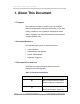
BSS C O NFI GUR ATI ON AND U SER G UIDE 1. About This Document 1.1 Purpose This document provides the details of various managed elements of base station subsystem (BSS) that you can add, modify, or delete by using operations management center (OMC). In addition, this document describes how to add and configure the BSS node. 1.
BSS C O NFI GUR ATI ON AND U SER G UIDE Convention Description system. Warning: Alerts you to potential injury or fatality. It may also alert you to potential electrical hazards. file/directory All courier new. names Bold font Any option that needs to be selected or typed in the user interface is represented using bold font. 1.
BSS C O NFI GUR ATI ON AND U SER G UIDE Terms / Abbreviations Description / Expansion DLA Dynamic Link Adaptation DLCI Data Link Connection Identifier DSP Digital Signaling Processing FCAPS Fault Configuration Accounting Performance and Security FCPS Fault Configuration Performance Security Page 12 FR Frame Relay FTP File Transfer Protocol GPRS General Packet Radio Service GUI Graphical User Interface HSN Hopping Sequence Number I/O Input/Output LAN Local Area Network LAPD
BSS C O NFI GUR ATI ON AND U SER G UIDE Terms / Abbreviations Description / Expansion MSC Mobile Switching Center NM Network Management NM/EM Network Management/Element Management ® NMS Network Management System NOC Network Operation Center NSVC Network Service Virtual Connection OID Object Identifier OMC Operations Management Center OSS Operations Support Systems PA Process Administration PDCH Packet Data Channel PS Packet Switch PID Process ID RA Routing Area REP Rem
BSS C O NFI GUR ATI ON AND U SER G UIDE Terms / Abbreviations Description / Expansion URL Uniform Resource Locator 1.
BSS C O NFI GUR ATI ON AND U SER G UIDE 2. BSS Overview The base station subsystem (BSS) is responsible for setting up, maintaining, and terminating the radio connections towards the mobile station (MS). BSS is a common resource where the same equipment and frequencies are used for both packet-switched and circuit-switched traffic. It can handle GSM 850, 900, 1800, and 1900 bands. The WorldGSM™ BSS supports both transmission distribution mode (TDM) and internet protocol (IP) interfaces.
BSS C O NFI GUR ATI ON AND U SER G UIDE • Base station controller (BSC) • Base transceiver station (BTS) BSC The BSC provides all the control functions and physical links between the mobile switching center (MSC) and BTS. BSC is a high-capacity switch that provides capabilities such as handover, cell configuration data, and control of radio frequency (RF) power levels in BTSs. In an area, the BTS connects to the BSC through the Abis interface. The BSC 500i is a table-top equipment.
BSS C O NFI GUR ATI ON AND U SER G UIDE The network management supports the configuration, supervision, and the maintenance of the network resources and services. VNL® network management provides the necessary input to higher service-level management, business support systems, and other administrative systems.
BSS C O NFI GUR ATI ON AND U SER G UIDE You can configure the time period for the reconciliation of a node. This periodic reconciliation of nodes is an automatic feature, which is on by default. Follow the below steps to configure the time period for the automatic reconciliation of node: 1. Open the Network Explorer window. 2. Select a node for which you want to configure the reconciliation time period. 3. Click Configuration, select Options, and click Reconcile Configuration. 4.
BSS C O NFI GUR ATI ON AND U SER G UIDE The Configuration – Modify Node window appears. 2. Right-click any node and click Search. The Search Element dialog box appears. 3. Type the name of the element in the Enter Element Name text box. 4. Click Find Next to search for the element mentioned in the text box. LNote: Click Find Next again, to search next instance of the mentioned text. 2.2 Administrative and Operational States of ME You can change the administrative state of MEs.
BSS C O NFI GUR ATI ON AND U SER G UIDE ME after performing the action. This changes the operational state of the ME to enable. • Unlock: In this state, you cannot perform any action on the ME. However, there is an exception with the cell table. You can modify the handover and power control parameters in unlocked state. 2.2.2 Operational States Operational state of a ME tells you the functional state of that ME. The change in the operational state of a ME depends on the internal working of BSC.
BSS C O NFI GUR ATI ON AND U SER G UIDE • Disconnect: Used to disconnect a ME from a network. • Shut Down Active: Used to shutdown a ME, which is in active state. The standby card becomes active. This puts the card in hot swap state (meant for maintenance purpose) and you can jack-out the card. This is also called as graceful shutdown of the processes. • Shut Down Standby: Used to shutdown a ME, which is in standby mode.
BSS C O NFI GUR ATI ON AND U SER G UIDE 3. Managing the BSS Node This section describes the procedure to add the BSS node in OMC. In addition, this section describes the different modes for viewing the BSS node and configuration of trunkport. 3.1 Adding a BSS Node The addition of BSS node in OMC is a two-step process: 1. The registration of BSS node with the OMC server. 2. Assigning the BSS node to hierarchy. Registration is an automatic process that BSS node initiates.
BSS C O NFI GUR ATI ON AND U SER G UIDE 3.1.1 Registering the BSS Node When you start (power-up) the BSS node, it initiates the registration process and sends its information to the OMC server. The IP address of the communicating OMC server is in the default factory settings of the BSS node. The following steps take place during the registration of the BSS node: 1. When BSS node is powered-up, it tries to connect to the designated OMC over transmission control protocol (TCP) interface. 2.
BSS C O NFI GUR ATI ON AND U SER G UIDE 3.1.2 Assigning the BSS Node to Hierarchy You can view the settings and configure the BSS node after moving the BSS node from unAssigned hierarchy to another hierarchy. The following are the steps to assign the BSS node to the default hierarchy: 1. Open the Network Explorer window and double-click unAssigned hierarchy. All the existing unAssigned nodes appear in right-pane. 2.
BSS C O NFI GUR ATI ON AND U SER G UIDE 3.2.1 Viewing Mode In this mode, you can only view the configuration details of a BSS node. You cannot edit any ME or fields of a ME. Follow the below steps to open a BSS node in the viewing mode: 1. Open the Network Explorer window. 2. Click the BSS node, click the Configuration menu, select Configuration, select View Node, and click Node Configuration. Alternatively, 2. Right-click a BSS node, select View Node, and click Node Configuration.
BSS C O NFI GUR ATI ON AND U SER G UIDE 2. Right-click a node, select Modify Node, and click Node Configuration. The Configuration – Modify Node window appears. 3. Double-click BSS: to view the MEs. 3.3 Configuring Trunkport A trunkport is an entity that connects switching centers or nodes in a communication network and handles many signals simultaneously. Trunkport facilitates the communication between any two network nodes (such as MSC-BSC, BSC-BTS, and so on) over E1.
BSS C O NFI GUR ATI ON AND U SER G Name UIDE Description Values associate with the EIC card. Options Activate Activates a TrunkPort trunkport. Deactivat Deactivates a e trunkport. - - TrunkPort TrunkPort Configuration Trunk Specifies the type trunk_E1_Type/trun Type of trunkport. k_T1_Type Framing Determines the bpm_Framing_Opt_ Option framing format to Crc4/bpm_Framing_ be used for E1 or Opt_NoCrc4 T1.
BSS C O NFI GUR ATI ON AND U SER Name G UIDE Description Values to this trunkport. At start-up, the usage type of all trunkports is free and is in deactivated state. Understanding Trunkport States The color scheme differentiates the trunkport states. The following colors are associated with the trunkport states: • Green: Trunkport is activated and enabled. • Blue: Trunkport is activated but disabled. • Red: Trunkport is deactivated and disabled.
BSS C O NFI GUR ATI ON AND U SER G UIDE 4. Select a trunk and click Modify. The lock or unlock option is automatically selected when you select a trunk. For example, for a locked trunk, the Unlock option is selected automatically. On successful lock or unlock, appropriate message appears. LNote: You cannot unlock a trunk with usage type free. 3.3.3 Activating Trunkport You should activate a trunkport before configuring other MEs of the BSS node.
BSS C O NFI GUR ATI ON AND U SER G UIDE should not be any BTS configured on Abis for that trunkport. The usage type of all internal trunkports is Abis. • Similarly, if you want to change usage type AIF to free or ABIS then these conditions should match: o AIF trunk must be in administratively locked state. o Message transfer part (MTP) link must not be configured on this AIF trunk. o Multilink point to point protocol (MLPPP) link must not be configured on this AIF trunk.
BSS C O NFI GUR ATI ON AND U SER G UIDE 4. Click an active trunkport. 5. Click Deactivate TrunkPort in the Options panel. 6. Click Modify to deactivate the trunkport. The Confirmation message box appears. 7. Click Ok. 3.4 Configuring MLPPP MLPPP is a communication protocol that enables a computer to use two point-to-point ports as a single port of greater bandwidth. Point-to-point protocol (PPP) is a fullduplex protocol that uses a serial interface for communication between systems.
BSS C O NFI GUR ATI ON AND U SER G UIDE The Configuration -Add Row dialog box appears. 3. Provide the details such as Node Ip, OMC Ip of the remote system, TrunkPort Number, and Time Slots. LNote: You can configure maximum eight Time Slots. 4. Click Ok to add MLPPP.
BSS C O NFI GUR ATI ON AND U SER G UIDE 4. BSC Configuration This section explains the procedure of adding BSC node and configuring timers. It also describes how you can perform modifications on the BSC node. 4.1 Adding BSC You can add only one BSC for a BSS node. Perform the following steps to add a BSC: 1. Open the BSS node in the modify mode. 2. Right-click the root node and click Add Element. 3. Select BSC from the ME Type drop-down list and click Ok.
BSS C O NFI GUR ATI ON AND U Name SER G UIDE Description Values OAM sets this parameters to false _Reset/active before it triggers platform to initiate a _ICC_Card_S reboot of BSS. This is a read-only field. hutdown/Stan dby_ICC_Car d_Shutdown Enable GPRS Defines whether BSS is supporting false/true GPRS service or not. If set to false, Gb interface and PS cells cannot be provisioned. Enable Call Indicates that the call reestablishment allowed, Re-Est is allowed or not.
BSS C O NFI GUR ATI ON AND U SER G UIDE Name Description Values NCC Indicates the network color code, which 0 to 7 is part of the BSIC. The BSIC is a local color code that allows a MS to distinguish between different neighboring base stations. Cell specific BCC is derived from ‘bcc’ from the cell table. Attribute is conveyed to BTS during configuration. NCC Provides a definition of the allowed Permitted NCCs on the BCCH carriers.
BSS C O NFI GUR ATI ON AND U SER G UIDE Name Description Values Min Freq While assigning multiple frequencies to 1 to 123 Channel Gap a cell, it is required to maintain a difference. For example, f1, f2, f3, f4 frequencies are assigned to one cell (all non BCCH). f1 < f2 < f3 < f4. Also, f2 – f1, f3 – f2, f4 – f3 should be >Min Freq Channel Gap. Tx Integer Indicates the number of slots to spread Value transmission on RACH (number of slots 0 to 15 in multi frame needed for transmission).
BSS C O NFI GUR ATI ON AND U Name SER G UIDE Description Values to circuit switch (CS) application used. Max Retrans Indicates the maximum number of Value retransmission on RACH. • 0 to 3 0: Maximum 1 retransmission • 1: Maximum 2 retransmissions • 2: Maximum 4 retransmissions • 3: Maximum 7 retransmissions tWaitCellBlock Indicates the timer for cell shutdown 30 to1800 procedure. Also, refer to “Administrative sec Operations”.
BSS C O NFI GUR ATI ON AND U Name SER G UIDE Description Values sending the handover-required message to MSC. tWaitTrxBlock Indicates the maximum allowed time 30 to1800 after which TRX is forcefully blocked. sec 4. In the Configuration – Add Row dialog box, provide the values and click Ok. This adds the BSC successfully in the selected BSS node. 4.2 Viewing BSC Details You can view and modify the details (fields) of BSC, which you have added.
BSS C O NFI GUR ATI ON AND U SER G UIDE Table 5: Fields in BSS PS Tab Name Description Values Network Mode Indicates the operation nmo_1/nmo_ Of Operation mode of the network. 2 Release of Indicates the release release_99_o SGSN number of serving r_higher/relea GPRS support node se_98_or_old (SGSN). er Indicates the signal 0 to 25 T_AVG_W strength filter period for power control in packet idle mode.
BSS C O NFI GUR ATI ON AND U SER G UIDE 4.3 Setting Administrative State of BSC There are different administrative states of BSC that you can set based on your requirement. For example, modifying the fields of BSC requires that the administrative state of BSC should be locked. Follow the below steps to perform any administrative action or to change administrative state of BSC: 1. Open the BSS node in the modify mode. 2. Expand BSC and right-click BSC: . 3.
BSS C O NFI GUR ATI ON AND U SER G UIDE 6. Click Ok. After modifying the fields, you should unlock the BSC to make the BSC operational. If the administrative state of BSC is unlocked then you cannot modify any fields of the BSC. In the unlocked state, the BSC is in operational state, which implies that BSC is communicating with BTS. 4.5 Configuring Timers Timers are preconfigured during factory setup. However, you can also configure the timers.
BSS C O NFI GUR ATI ON AND U SER G UIDE The below sections give the description of fields of all timers. 4.5.1 BSSAP Timers BSSAP timers show the BSSAP stack timer values. You can change the field values within the given range for each field. The following table provides the details of the BSSAP timers: Table 6: BSSAP Timers Fields Field Name Description Values (seconds) T1 BSSAP timer value T1 1 to300 time to receipt of (UN)BLOCKING ACKNOWLEDGE message at the BSS.
BSS C O NFI GUR ATI ON AND U SER G UIDE Field Name Description T13 BSSAP timer value T13 Values (seconds) reset guard period at the BSS to send RESET-ACK mesasge to MSC. T17 Overload timer for access class barring procedure. T18 Overload timer for access class unbarring procedure. T19 BSSAP timer value T19 time to receipt of RESET CIRCUIT ACKNOWLEDGE message at the BSS. T20 BSSAP timer value T20 time to receipt of CIRCUIT GROUP BLOCKING ACKNOWLEDGE message at the BSS. 4.5.
BSS C O NFI GUR ATI ON AND U SER G UIDE The following table provides the details of the MTP3 timers: Table 7: MTP3 Timers Fields Field name Description Values T1 Specifies the MTP3 5 to 12 msec timer value T1. T2 Specifies the MTP3 7 to 20 msec timer value T2. T3 Specifies the MTP3 5 to12 msec timer value T3. T4 Specifies the MTP3 timer value T4. T5 Specifies the MTP3 timer value T5. T6 Specifies the MTP3 timer value T6. T7 Specifies the MTP3 10 to 20 msec timer value T7.
BSS C O NFI GUR ATI ON AND U SER G UIDE Field name Description Values T11 Specifies the MTP3 300 to 900 timer value T11. msec Specifies the MTP3 8 to15 msec T12 Timer value T12. T13 Specifies the MTP3 Timer value T13. T14 Specifies the MTP3 20 to 30 sec Timer value T14. T15 Specifies the MTP3 timer value T15. T16 Specifies the MTP3 14 to 20 msec timer value T16. T17 Specifies the MTP3 8 to15 msec timer value T17. T18 Specifies the MTP3 20 to 500 sec timer value T18.
BSS C O NFI GUR ATI ON AND U SER Field name G UIDE Description Values timer value T22. T23 Specifies the MTP3 timer value T23. T24 T25 Specifies the MTP3 10 to 3600 timer value T24. msec Specifies the MTP3 300 to 350 sec timer value T25. T26 Specifies the MTP3 120 to150 sec timer value T26. T27 Specifies the MTP3 20 to 50 sec timer value T27. T28 Specifies the MTP3 30 to350 sec timer value T28. T29 Specifies the MTP3 600 to 650 sec timer value T29.
BSS C O NFI GUR ATI ON AND U SER G UIDE Field name Description Values T34 Specifies the MTP3 1 to100 sec timer value T34. 4.5.3 PDC Timers You can change the field values within the given range for each field. To modify the fields of the PDC Timers tabbed page, node lock is not required. The following table provides the details of the PDC timers: Table 8: PDC Timers Configuration Fields Field Name Description Values PDC General Indicates the PDC timer 10_min/15_m Timer value.
BSS C O NFI GUR ATI ON AND U SER G UIDE Table 9: SCCP Timers Fields Field Name Description Values (seconds) Stat Info Indicates the retry for 5 to1200 SST timer. Coord Chg Indicates the wait for 60 to120 grant of SS to go out of service, timer. Ig0reSST Indicates the difference 30 to 60 between the actual and the received grant of SS to go out of service. TgStatInfo Indicates the 30 to 60 T_rtgstat_info timer value. Conn Indicates the incoming 60 to120 connection timer.
BSS C O NFI GUR ATI ON AND U SER G UIDE Field Name Description Values (seconds) Guard Indicates the restart 60 to 660 guard timer. Reassembly Indicates the 10 to 20 reassembly timer. Interval Indicates the interval 1 to 60 timer. Repeat Release Indicates the repeat 1 to 20 release timer.
BSS C O NFI GUR ATI ON AND U SER G UIDE 5. Stack Configuration This section describes the configuration of signaling system (SS) number7 stack. You can add, remove, or modify MEs in the stack. 5.1 Configuring SS7 Stack SS 7 provides the basis for the signaling traffic on all network switching subsystems (NSSs) and A-Interface to the layers 1 to 3 of the open systems interconnection (OSI) model. LNote: BSC should be in locked state to add, modify, or delete the stack configuration.
BSS C O NFI GUR ATI ON AND U SER G Field Name UIDE Description Values code. Family Specifies the standard. itu/ansi LNote: Only SS7_FAMILY_ITU family supported. Alarm Indicates the alarm level to alarm_Level Level be set. _Info/alarm_ Level_Major /alarm_Leve l_Minor/alar m_Level_Cri tical 3. Provide the values in the specified fields and click Ok to configure the stack. LNote: You can configure only one stack for a BSC. 5.1.
BSS C O NFI GUR ATI ON AND U SER G UIDE 2. Expand StackConfig, right-click SS7 Stack, and click Add AInterface. The Configuration- Add Row dialog box appears. The configurable fields of the AInterface Add Row dialog box are described in the following table: Table 11: AInterface Configuration Fields Field Name Description Value Interface ID Refers to the unique identifier 1 to 127 to identify an interface. Interface Name Indicates the name of the 1 to 20 interface for display purposes.
BSS C O NFI GUR ATI ON AND U SER G UIDE LNote: You can perform only add or delete functions on AInterface table and can add maximum one row for AInterface. 5.1.2 Configuring TrunkGroup Trunk group is the collection of trunks/lines that carry incoming and outgoing traffic in order to establish connection between switching systems. This section describes how you can configure TrunkGroup. 5.1.2.1 Adding TrunkGroup The TrunkGroup automatically adds in the AIF ME when you add AInterface.
BSS C O NFI GUR ATI ON AND U SER G UIDE The Configuration - Add Row dialog box appears. The configurable fields for the trunk configuration are described in the following table: Table 12: AIFTrunk Configuration Fields Field Name Description Values Interface Id Uniquely identifies an - interface. Trunk Group Id Indicates the trunk group - id to which this E1 belongs. Trunk Port ID Indicates the trunkport 0 to 39 id. Trunk Type Indicates the type of trunk_E1_Type trunk that is E1 or T1.
BSS C O NFI GUR ATI ON AND U SER G UIDE 5.1.3 Adding LinkSet There is only one linkset between BSC and MSC. Therefore, you cannot add more than one linkset. Follow these steps to add a linkset: 1. Open the BSS node in the modify mode. 2. Expand StackConfig, expand SS7 Stack, right-click AIF, and select Add LinkSet. The Configuration – Add Row dialog box appears.
BSS C O NFI GUR ATI ON AND U SER G Field Name UIDE Description Values rnational_Reserved 3. Provide the values in the specified fields. 4. Click Ok to add the link. LNote: Operation state of link is set to automatic startup (operational state field). 5.1.3.1 Adding Link Link shows MTP2 link related fields. A trunkport with usage type AIF should be enabled and in active state to add a link. The Trunk Port ID field of Link Configuration dialog box automatically populates.
BSS C O NFI GUR ATI ON AND U SER G UIDE Table 14: Link Configuration Fields Field Name Description Values Indicates the linkset id. This - Link Set ID is a read-only field. Link ID Indicates the link id. 0 to 15 Indicates the signaling link 0 to 15 code. This is a read-only SLC field. Trunkport id carrying MTP2 Trunk Port ID 0 to 39 link. Indicates the timeslot on the If TrunkType is E1: 1 trunkport id carrying MTP2 to 31 link.
BSS C O NFI GUR ATI ON AND U SER Field Name G UIDE Description Values read-only field. false/true Indicates that whether satellite link is enabled or Satellite Flag not. 5. Provide the required values and click Ok to add link. 5.1.3.2 Locking/Unlocking Link You can perform lock or unlock action on a link by following the below steps: 1. Open the BSS node in the modify mode. 2.
BSS C O NFI GUR ATI ON AND U SER G UIDE 2. Expand Link and click Link :. 3. In the Link tab, select values from TrunkPort ID, Satellite Flag and Time Slot drop-down lists for trunkport id, satellite flag, and time slot respectively. 4. Click Modify to save the changes. You should change the administrative state to unlock after saving the changes. The operational state changes to enabled when you change the administrative state to unlock.
BSS C O NFI GUR ATI ON AND U Field Name SER G UIDE Description Values is a read-only field. Route ID Indicates the unique route ID. 1 to 100 Route Name Indicates the name of the 1 to 19 route to be displayed. Style dpc-ni/dpc-sio-ssn Defines the route parameter as destination point codeservice indicator octet (SIO) and subsystem number (SSN). DPC Indicates the destination point 1 to 16383 code. Interface Indicates the type of if_Type_Aif Type interface. This is a read-only field.
BSS C O NFI GUR ATI ON AND Field Name U SER G UIDE Description Values procedure is to be enabled or not. Its value depends on the Style field with the following condition: • If Style= dpc-ni then SST Test On = disable • If Style= dpc-sio-ssn then SST Test On= enable 4. Provide the values in the specified fields and click Ok. LNote: You have to add two SS7 routes for A-Interface. 5.
BSS C O NFI GUR ATI ON AND U SER G UIDE Here, as an example, the Lock option is selected which opens the Lock dialog box. 4. Click Ok to close the Lock dialog box. 5.2.2 Deleting AIFTrunk The administrative state of all CIC in the AIFTrunk should be locked. Follow these steps to delete AIFTrunk: 1. Lock all CIC in the AIFTrunk. Refer “Locking/Unlocking CIC“for more details. 2. Right click AIFTrunk and click Delete. 3. Click Yes. 5.2.
BSS C O NFI GUR ATI ON AND U SER G UIDE 2. Expand SS7 Route, right-click a SS7Route :, and click Delete. Alternatively, in the SS7Route tab, click Delete. 5.2.5 Deleting Link You should lock the link before deleting it. Follow these steps to delete link: 1. Lock Link. Refer “Locking/Unlocking Link “for more details. 2. Right click Link and click Delete. 3. Click Yes. 5.2.6 Deleting A-Interface The administrative state of all CIC should be locked, if you want to delete A-Interface.
BSS C O NFI GUR ATI ON AND U SER G UIDE 6. Radio Network Configuration This section describes the configuration of radio network MEs. You can add, remove, or modify MEs in the RadioConfig ME. 6.1 Configuring ARFCN The absolute radio frequency channel number (ARFCN) specifies a pair of physical radio carriers and channels used for transmission and reception on the Um interface, one for the uplink and one for the downlink signal. 6.1.1 Adding ARFCN You can only add or delete ARFCN.
BSS C O NFI GUR ATI ON AND U SER G UIDE 6.1.2 Viewing ARFCN You can view the details of ARFCN by following the below steps: 1. Open the BSS node in the modify mode. 2. Expand RadioConfig and click ARFCN to view the Absolute Radio Frequency Channel Number tabbed page. The following table lists valid ARFCN values for different frequency bands: Table 16: Valid ARFCN Values Frequency Band ARFCN Value Range gsm850 128 to 251 gsm900 1 to 124 gsm1800 512 to 885 gsm1900 512 to 810 6.1.
BSS C O NFI GUR ATI ON AND U SER G UIDE 3. In the Absolute Radio Frequency Channel Number tab, select a row and click Delete. 4. Click Yes to delete the selected row. 6.2 Configuring CsExternalCell The CsExternalCell ME shows list of external CS cells. The cell ids of external cells, which are neighbor to CS cells, are added to ‘CSNeighCells’ relation table. You can add, delete, or modify fields of the CsExternalCell ME without locking the BSS. 6.2.
BSS C O NFI GUR ATI ON AND U SER G UIDE Field Name Description Values MNC Indicates the mobile network 0 to 9 code. LAC Indicates the location area 1to 65533, 65535 code. External CS external (cell belongs to CellId other BSS or network) cell 0 to 65535 identifier. BCC Indicates the base station 0 to 7 color code (BCC). This is a part of the BSIC. The BSIC is a local color code that allows a MS to distinguish between different neighboring base stations.
BSS C O NFI GUR ATI ON AND Field Name U SER G UIDE Description Values This frequency is used by an GSM 1800: 512 to 885 idle MS for cell reselection. Frequency Indicates the frequency band gsm900/gsm1800/gsm8 Band of the BCCH frequency 50/gsm1900 supported by the cell. MS_TXPW Indicates the maximum TX 0 to 15, 5 to 19 R_MAX power a MS is permitted to GSM 900: 0 to 15 use on a dedicated control GSM 1800: 5 to 19 channel or a traffic channel within the cell.
BSS C O NFI GUR ATI ON Field Name AND U SER G UIDE Description Values .. • 14: 2 dBm 2 dBm • 15: 0 dBm 0 dBm • 29: 36 dBm N/A • 30: 34 dBm 34 dBm • 31: 32 dBm 32 dBm 5. Click Ok to add the new row. 6.2.2 Modifying CsExternalCell You can change the values of fields of a CsExternalCell. Perform the below steps to modify fields of the CsExternalCell ME: 1. Open the BSS node in the modify mode. 2. Expand RadioConfig and click CsExternalCell. 3. Select a row from the table. 4.
BSS C O NFI GUR ATI ON AND U SER G UIDE 6.2.3 Deleting CsExternalCell You can delete a CsExternalCell based on your requirement. The deletion of a row from CsExternalCell deletes the corresponding CsExternalCell. Perform the below steps to delete a CsExternalCell ME: 1. Open the BSS node in the modify mode. 2. Expand RadioConfig and click CsExternalCell. 3. Select a row from the table and click Delete. 4. Click Yes to delete the selected row. 6.
BSS C O NFI GUR ATI ON AND U SER G UIDE Table 18: LAC Fields Field Name Description Values LAC Indicates the location 1 to 65533, area code. 65535 4. Click Ok to add the new LAC. As shown in the figure given below the LAC has no data to modify, it has only index value that cannot be modified. Similarly, you can delete a LAC by clicking Delete in the LAC tab. 6.4 Configuring Cell Cell is the unit of radio coverage area.
BSS C O NFI GUR ATI ON AND U SER G UIDE 2. Expand RadioConfig and click LAC. 3. Right-click LAC : and click Add Element. 4. In the Add Element dialog box, select CELL from the ME Type list and click Ok. 5. In the Configuration – Add Row dialog box provide the values.
BSS C O NFI GUR ATI ON AND U SER G UIDE Field Name Description Values BCCH Power Defines the downlink power of the 0 to 127 Level BCCH carrier. MS_TXPWR_M Indicates the maximum TX power an AX MS is permitted to use on a dedicated 0 to 15, 5 to 19 control channel or a traffic channel within the serving cell.
BSS C O NFI GUR ATI ON AND Field Name U SER G UIDE Description GSM1800 Values GSM1900: • 0: 30 dBm 30dBm • 1: 28 dBm 28dBm • .. .. .. • 14: 2 dBm 2 dBm • 15: 0 dBm 0 dBm • 29: 36 dBm N/A • 30: 34 dBm 34 dBm • 31: 32 dBm 32 dBm MS_TXPWR_M Indicates the maximum transmit power ax_C level an MS may use in the cell when 0 to 15, 5 to19 accessing on the common control channel. This parameter is also used for the C1 cell (re)selection criteria.
BSS C O NFI GUR ATI ON AND Field Name U SER G UIDE Description Values • 14: 2 dBm 2 dBm • 15: 0 dBm 0 dBm • 29: 36 dBm N/A • 30: 34 dBm 34 dBm • 31: 32 dBm 32 dBm FrameNum Frame number offset is used to Offset decrease interference of synchronized 0 to 25 neighbor cells in case of frequency hopping. psAllowed This indicates whether PS is allowed in notAllowed/allowed this cell or not.
BSS C O NFI GUR ATI ON AND U SER G UIDE Field Name Description Values BS_PA_MFRM Indicates the number of multi frames 0 to 7 S period for transmission of paging request messages to the same paging subgroup. (Number of multi frames = BS_PA_MFRMS + 2) CELL_RESELE Indicates the dB RXLEV hysteresis for CT_HYST LA re-selection.
BSS C O NFI GUR ATI ON AND Field Name U SER G UIDE Description Values 1: 2 dB power offset 2: 4 dB power offset 3: 6 dB power offset Cell Bar Qualify Cell bar qualify is used by the network 0 to 1 to control mobile station cell selection and reselection. CELL_RESELE Used by the mobile station to apply a CT_OFFSET positive or negative offset to the value 0 to 63 of C2 as defined in 3GPP TS 23.022 and 3GPP TS 45.008.
BSS C O NFI GUR ATI ON AND Field Name U SER G UIDE Description Values HR provides the option of utilizing the same timeslots (8) for more number of users. This is a read-only field. Initial AMR Refers to the codec, which AMR uses. Codec Rate This is set to 5.90 and you cannot amr_590 modify it. FR to HR Switch You can select the percentage of full or Percentage half rate while using AMR. Max value of Indicates to the maximum value of Timing Advance acceptable timing advance.
BSS C O NFI GUR ATI ON AND U SER G UIDE 1. Open the BSS node in the modify mode. 2. Expand RadioConfig, expand LAC, and right-click the desired cell. 3. Select Actions. 4. Click the required state. Lock, Block, or Unlock dialog box appears based on the selection. Here, the Unlock dialog box is shown. 5. Click Ok to lock/unlock/block the cell. 6.4.3 Viewing Cell Operational State You can view the operational status of the cell in the Operational State tab of cell.
BSS C O NFI GUR ATI ON AND U SER G UIDE The configurable fields for configuring the internal neighbor cell are described in the following table: Table 20: Internal Neighbor Cell Fields Field Name Description Values LAC Indicates the location area code. 1 to 65533, 65535 Neighbour MCC Indicates the neighbor cell mobile 0 to 999 country code. Relation Type Indicates the relation type. actidle RX Level MinN Indicates the minimum BCCH 0 to 63 receive level for neighbor cell (n).
BSS C O NFI GUR ATI ON AND U SER G UIDE Field Name Description Values Neighbour Cell Indicates the neighbor cell identifier. 0 to 65535 ID Given below is the figure for the external cell neighbor and its field description: The fields of the external neighbor cell are described in the following table: Table 21: External Neighbor Cell Fields Field Name Description Values LAC Indicates the location area code of 1 to 65533, serving cell.
BSS C O NFI GUR ATI ON AND U SER G UIDE Field Name Description Values Rx Level Min Indicates the minimum BCCH 0 to 63 receive level for neighbor cell (n) which must be reported for a respective neighboring cell 'n' before the MS is allowed to handover to this particular cell. 0: < -110 dBm 1: -110dBm.-109dBm 2: -109dBm.-108dBm 62: -49dBm.-48dBm 63: >-48dBm Ho Margin N Indicates the handover margin for -128 to 127 neighbor cell N. 5. Provide values in the specified fields and click Ok. 6.4.
BSS C O NFI GUR ATI ON AND U SER G UIDE 6.4.6 Configuring Cell Handover You can configure handover parameters for a cell. The HandOver tab allows you to add, modify, or delete the fields of the Handover tab for cell. Cell lock is not required for modifying cell parameters. Cell lock is required to delete a cell. In addition, handover parameters are added in cell locked state. If you do not add the handover parameters then cell unlock fails.
BSS C O NFI GUR ATI ON AND U SER G UIDE The configurable fields of the HandOver tabbed page are described in the following table: Table 22: Handover Configuration Fields Field Name Description Values LAC Indicates the location area code of the cell. 1 to 65533, 65535 Cell ID Refers to the cell identifier. 0 to 65535 Enable HO Enables handover based on receive level true/false RxLev (enables both uplink and downlink).
BSS C O NFI GUR ATI ON AND Field Name U SER G UIDE Description Values values) WindowSize RxQual ≥ WindowSize RxLev_Ncell WindowSize Indicates the size of the averaging windows RxLev_Ncell for RXLEV_NCELL for all neighbor cells. 1 to 10 Consistency Conditions: WindowSize RxLev_Ncell ≤ WindowSize RxLev WindowSize RxLev_Ncell ≤ WindowSize RxQual Min Rx Lev DL Indicates the handover threshold for downlink HO receive level (RXLEV_DL).
BSS C O NFI GUR ATI ON AND Field Name U SER G UIDE Description Values Min Rx Lev DL HO < RX Level MinN (CsNeighCells) of all configured neighbor cells of this cell Min Rx Lev UL Indicates the handover threshold for uplink HO receive level (RXLEV_UL). • 0 to 63 0: measured signal level < 110 dBm • 1: -110 dBm < measured signal level < -109 dBm • 2: -109 dBm < measured signal level < -108 dBm.
BSS C O NFI GUR ATI ON AND Field Name U SER G UIDE Description • 6: 6.4 % < BER < 12.8 % • 7: 12.8 % < BER Values Consistency Conditions: Min Rx Qual Lev DL HO > Max Rx Qual UL Min Rx Qual Lev Indicates the handover threshold for uplink UL HO receive quality. • 0: BER < 0.2 % • 1: 0.2 % < BER < .4 % • 2: 0.4 % < BER < 0.8 % • 3: 0.8 % < BER < 1.6 % • 4: 1.6 % < BER < 3.2 % • 5: 3.2 % < BER < 6.4 % • 6: 6.4 % < BER < 12.8 % • 7: 12.
BSS C O NFI GUR ATI ON AND Field Name U SER G UIDE Description • Values 2: report 2 strongest cells from other band • 3: report 3 strongest cells from other band Enable Incoming Enables or disables incoming handovers. 0 to 1 HO 5. Edit the fields. 6. Click Ok to add the handover details. LNote: Similarly, you can modify the fields of the HandOver tab. In order to modify any field, edit the required fields and click Modify to save the changes.
BSS C O NFI GUR ATI ON AND U SER G UIDE 4. Click Add. The configurable fields of the Power Control tabbed page are described in the following table: Table 23: Cell Power Control Fields Field Name Description Values LAC Indicates the location area code of the cell. 1 to 65533, 65535 Cell ID Refers to the cell identifier. 0 to 65535 Enable MS Controls, if UL power control (that is control of true/false PWR CTRL MS Tx power) is activated/deactivated in a cell.
BSS C O NFI GUR ATI ON AND Field Name U SER G UIDE Description Values level Consistency Conditions: Min Rx Lev UL < Max Rx Lev UL Max Rx Lev UL - Min Rx Lev UL > incrStepSizeP Max Rx Lev UL - Min Rx Lev UL > safetyMarginP Min Rx Lev UL HO < Min Rx Lev UL Max Rx Lev UL Indicates the upper threshold for the Rx power 0 to 63 level measured on uplink. If the BTS/TRX reports a higher level, the uplink power is reduced.
BSS C O NFI GUR ATI ON Field Name AND U SER G UIDE Description Values incrStepSizeP Max Rx Lev UL - Min Rx Lev UL > safetyMarginP Min Rx Qual Refers to the threshold that defines lowest UL acceptable quality measured on the uplink. 0 to 7 If the BTS/TRX reports a lower quality, the uplink power is increased. • 0: BER < 0.2 % • 1: 0.2 % < BER < 0.4 % • 2: 0.4 % < BER < 0.8 % • 3: 0.8 % < BER < 1.6 % • 4: 1.6 % < BER < 3.2 % • 5: 3.2 % < BER < 6.4 % • 6: 6.4 % < BER < 12.
BSS C O NFI GUR ATI ON AND Field Name U SER G UIDE Description Values • 2: 0.4 % < BER < 0.8 % • 3: 0.8 % < BER < 1.6 % • 4: 1.6 % < BER < 3.2 % • 5: 3.2 % < BER < 6.4 % • 6: 6.4 % < BER < 12.8 % • 7: 12.8 % < BER Consistency Condition: Min Rx Qual UL > Max Rx Qual UL Min Rx Lev DL Indicates the lower threshold for the Rx power 0 to 63 level measured on the downlink. If the MS reports a lower level, the downlink power can be increased.
BSS C O NFI GUR ATI ON AND Field Name U SER G UIDE Description Values incrStepSizeP Max Rx Lev DL - Min Rx Lev DL > safetyMarginP Min Rx Lev DL HO < Min Rx Lev DL Max Rx Lev DL Indicates the upper threshold for the Rx power 0 to 63 level measured on the downlink. If the MS reports a higher level, the downlink power is reduced.
BSS C O NFI GUR ATI ON AND Field Name U SER G UIDE Description Values the MS reports a lower quality, the downlink power is increased. • 0: BER < 0.2 % • 1: 0.2 % < BER < 0.4 % • 2: 0.4 % < BER < 0.8 % • 3: 0.8 % < BER < 1.6 % • 4: 1.6 % < BER < 3.2 % • 5: 3.2 % < BER < 6.4 % • 6: 6.4 % < BER < 12.8 % • 7: 12.
BSS C O NFI GUR ATI ON Field Name AND U SER G UIDE Description • 6: 6.4 % < BER < 12.8 % • 7: 12.8 % < BER Values Consistency Condition: Max Rx Qual DL > Min Rx Qual UL 5. Click Ok to add the details. LNote: Similarly, you can modify the fields in the Power Control tab. In order to modify any field, edit the required fields and click Modify to save the changes. Similarly, you can also delete all the power control details of a cell by clicking Delete in the Power control tab.
BSS C O NFI GUR ATI ON AND U SER G UIDE 6.4.9 Configuring Channel Group Channel group (CHNGRP) is a list of channels based on their common characteristics. Each cell can have multiple channel groups associated with it. You can add, modify, or delete the fields in the CHNGRP tab of the CHNGRP ME. LNote: Lock the cell to perform add, delete, or modify operations. 6.4.9.1 Adding Channel Group Follow the below steps to add channel group: 1. Open the BSS node in the modify mode. 2.
BSS C O NFI GUR ATI ON AND Field Name U SER G UIDE Description Values BCCH Ccch Refers to the number of combined 0 to 1 Sdcch4 BCCH + SDCCH/4. Bcch Ccch Indicates the number of standalone Group Id 0 to1 BCCH/CCCH. SDCCH8 Indicates the number of SDCCH8. 0 to 2 dualTraffic Indicates the number of dual traffic 0 to 47 channels (TCHs and PDCHs). HSN Indicates the hopping sequence 0 to 63 (0 = number.
BSS C O NFI GUR ATI ON AND U SER G UIDE Field Name Description Values Num of Defines the number of valid ARFCNs of 1 to 17 Valid Arfcns subsequent list. ARFCN1 Indicates the absolute radio frequency 1 to 124, 512 to number. 885, 128 to 251, 512 to 810, 65535 GSM 900: 1 to 124 GSM 1800: 512 to 885 GSM 1900: 512-810, GSM 850: 128251 …. ARFCN17 Indicates the absolute radio frequency 1 to 124, 512 to number.
BSS C O NFI GUR ATI ON AND Field Name U SER G UIDE Description Values 251 CBCH Allows cell broadcast service in the true/false selected cell. If set to false then cell broadcast service is disabled in the selected cell. It should be set to true if you want to enable cell broadcast service in the selected cell. MAIO Specifies the mobile allocation index 0 to 16 offset (MAIO).
BSS C O NFI GUR ATI ON AND U SER G UIDE 6.4.9.3 Deleting Channel Group You can delete the channel group. LNote: The administrative state of cell should be locked to delete the channel group. Follow the below steps to delete the channel group: 1. Open the BSS node in the modify mode 2. Expand RadioConfig, expand LAC, expand LAC :, expand CELL :, right-click a CHNGRP and click Delete. Alternatively, 2. Click Delete from the CHNGRP tab. 3. Click Yes to delete the CHNGRP. 6.4.
BSS C O NFI GUR ATI ON AND U SER G UIDE 6.5.1 Adding BTS A trunkport with usage type Abis should be enabled and in active state to add a BTS. The Trunk Port ID field of Configuration - Add Row dialog box automatically populates. Therefore, if no trunkport is configured then you cannot add BTS. Refer “Configuring Trunkport ” to know how to enable and activate a trunkport. A BSS can have one or more BTS. An ABIS interface is implemented between the BSC and each BTS. Follow these steps to add BTS: 1.
BSS C O NFI GUR ATI ON AND Name U SER G UIDE Description Values and 51 to 58 indicate internal trunks. Admin State Indicates the administrative state of BTS. locked/unlocke This is a read-only field. d BTS type Identifies the type of BTS. r2_BTS BTS Name Indicates the operator specified display 1 to 19 string to identify a BTS by name. characters Connectivity Indicates the operator specified BTS connect/discon State connectivity state.
BSS C O NFI GUR ATI ON AND U SER G UIDE In addition, you can perform these actions on BTS: • Disconnect: This means that BTS is not connected to BSC as the BTS link access protocol-channel D (LAPD) link is down. • Connect: This means that BTS is connected to the BSC. • Reset BTS: This is used to restart/reset the BTS. Follow these steps to set any of the above state or perform any action on BTS: 1. Open the BSS node in the modify mode. 2.
BSS C O NFI GUR ATI ON AND U SER G UIDE 6.5.4 Adding TRX You can add the same number of TRX that you have specified during the addition of BTS. If you have not specified any TRX for a BTS then you cannot add any TRX for the BTS. In addition, you cannot modify the Number of Trx field of BTS after the addition of BTS. Therefore, you can only add the number of TRX as specified in BTS configuration. Follow these steps to add a TRX: 1. Open the BSS node in the modify mode. 2.
BSS C O NFI GUR ATI ON AND Field Name U SER G UIDE Description Values the TRX. This is a read-only field. TRX Location Defines the location of TRX whether r2_BTS in the frame or with R2 BTS. This is a read-only field. Antenna lD Antenna identifier for association of 0 to 4294967295 TRX with a cell. TRX Position Specifies the position of the TRX 1 to 2 within a BTS. RF PathGain Adds all positive and negative -32768 to 32767 attenuation gains. 4.
BSS C O NFI GUR ATI ON AND U SER G UIDE 6.5.6 Settings Administrative State of TRX You can lock, unlock, reset (TRX should be locked and is applicable for the non BCCH TRX), and block a TRX. Follow these steps to lock/unlock the TRX: 1. Open the BSS node in the modify mode. 2. Expand BTS-IF, expand BTS :,click TRX, and right-click TRX :. 3. Select Actions and select the state that you want to select for the TRX from the short-cut menu.
BSS C O NFI GUR ATI ON AND U SER G UIDE LNote: To delete you should first lock the TRX. Follow these steps to delete BTS TRX: 1. Open the BSS node in the modify mode. 2. Expand BTS-IF, expand BTS :, and click TRX. 3. Right-click TRX : and select TRX that you want to delete or click Delete from the TRX tab. The Delete Data dialog box appears. 4. Click Yes to delete the selected TRX. 6.5.9 Deleting BTS Follow these steps to delete a BTS node: 1.
BSS C O NFI GUR ATI ON AND U SER G UIDE 7. GPRS Configuration General packet radio service (GPRS) introduces packet switching to the GSM network. It integrates with the existing GSM systems; reuses the GSM radio network infrastructure and the same transmission links (with few more links such as Gb, Gs, Gr, and others) between the GSM network nodes. This section explains how you can configure GPRS in the BSS. The following flow chart depicts the steps for configuring GPRS: 7.
BSS C O NFI GUR ATI ON AND U SER G UIDE The above two fields are explained below: Table 27: Fields in RA Configuration Field Description Values LAC Indicates the location area 1 to 65533, code to which the RAC 65535 belongs. This is a read-only field. RA Indicates the routing area 0 to 255 code. 5. Provide valid values in the LAC and RA text boxes. 6. Click Ok. RA is added in the left pane. The various fields in the PsCell tabbed page are explained in “Table 28”. 7.1.
BSS C O NFI GUR ATI ON AND U SER G UIDE 7.2 Configuring Cell Level GPRS Data You can add, modify, or delete the fields of this ME only when the administrative state of the cell is locked. The subsequent sections explain the procedure of adding, modifying, and deleting GRPS details in the BSS. 7.2.1 Adding Cell Level GPRS Data Follow the below steps to add GPRS details: 1. Open the BSS node in the modify mode. 2. Expand RadioConfig, expand LAC, expand LAC: , and click CELL: .
BSS C O NFI GUR ATI ON AND U SER Field G UIDE Description Values corresponding CS cell in “Table 19”. This is a readonly field. Routing Area Indicates the routing 0 to Code area code. 255 RA Color Indicates the routing area 0 to color.
BSS C O NFI GUR ATI ON AND U SER G UIDE Field Description Values channels that are reserved for PDCH in the cell. Max TBF Indentifies the maximum 1 to 7 number of TBFs per direction that can be multiplexed on a PDCH in this PS cell. SSB Indicates the intended 0 to 63 received signal strength of a block at the BTS for GPRS uplink open loop power control. Priority Access Indicates the allowed 0 to 7 priority of packet access in the cell.
BSS C O NFI GUR ATI ON AND U SER G UIDE Field Description Values Consistency Conditions: GPRS CS Initial<= GPRS CS Max GPRS CS Initial Provides the initial coding cs_1, scheme to be used in a cs_2, TBF. If DLA is disabled, cs_3, the initial coding scheme cs_4 is used for all RLC data blocks of a TBF. Consistency Conditions: GPRS CS Initial<= GPRS CS Max percFreeCsChannels Defines the relative 0..
BSS C O NFI GUR ATI ON AND U SER G UIDE Field Description Values activation after a previous PDCH reduction was triggered. An absolute number numFreeCsChannelsHy st can be calculated out of percFreeCsChannelsH yst. This is rounded-up to the next integer value, but is always less than the number of all configured dual service timeslots. 4. Provide valid values in relevant fields and click Ok.
BSS C O NFI GUR ATI ON AND U SER G UIDE percFreeCsChannels and minNumPdchCell, rounded up to the next integer value. 7.2.2 Setting Administrative States of PS Cell You can perform the following actions on the PS cell: • Block • Lock • Unlock Follow the below steps to perform any of the above actions: 1. Open the BSS node in the modify mode. 2. Expand RadioConfig, expand LAC, expand LAC: , right-click CELL: , and select the desired option.
BSS C O NFI GUR ATI ON AND U SER G UIDE 7.2.4 Deleting Cell Level GPRS Data Follow the below steps to delete the details in the GPRS Data tabbed page: 1. Open the BSS node in the modify mode. 2. Expand RadioConfig, expand LAC, expand LAC: , and click CELL: . 3. Click GPRS Data tab and click Delete. This deletes the details in the GPRS Data tabbed page. 7.3 Configuring Gb Interface The Gb interface exists between the BSS and serving GPRS support node (SGSN) in a GPRS network.
BSS C O NFI GUR ATI ON AND U SER G UIDE Table 29: Fields in GB Interface Tab Field Name Description Values nsei 0 to 65535 Indicates the network service entity identifier. Max Indicates the maximum Number of number of NSVCs that NSVCs can be provisioned for the over FR system, when FR 1 to 26 transport is used. Max Indicates the maximum Number of number of NSVCs that NSVCs can be provisioned for the over IP system, when IP transport 1 to 65535 is used.
BSS C O NFI GUR ATI ON AND U SER G UIDE Field Name Description Values tFcC 1 to 10 Timer C for Gb flow control. It indicates the minimum interval between sending of subsequent flow control PDUs for a given BVC or MS. This value needs to be aligned with the SGSN settings. Consistency Conditions: tFcTh > tFcC tFcTh 5 to 6000 Timer Th for Gb flow control.
BSS C O NFI GUR ATI ON AND U SER G UIDE Field Name Description Values Unit: 100 ms Consistency Conditions: tFcSup* (nMaxFcRep+1) < tFcC nMaxFcRep Indicates the maximum 1 to 3 number of repetitions for flow control message. Consistency Conditions: tFcSup* (nMaxFcRep +1) < tFcC tWaitConfig Guards the SGSN initiated 10 to 100 configuration procedure when transport type is ip_dyanmic. Operational Indicates the Gb Status operational state.
BSS C O NFI GUR ATI ON AND U SER G UIDE Field Name Description Values Operational Status filed is enabled. LNote: The data present in the GB Interface tabbed page is preconfigured and is read from the BSS. 7.3.2 Modifying Gb Interface Details You must lock the GB Interface to modify it. You can modify the details in the GB Interface tab by following the below steps: 1. Open the BSS node in the modify mode. 2. Expand StackConfig and click GB Interface. 3.
BSS C O NFI GUR ATI ON AND U SER G UIDE The Configuration – Add Row dialog box appears. The various fields are explained in the following table: Table 30: FR Fields Field Name Description Values FR Channel ID Indicates the unique 1 to maximum FR channel number of identifier. NSVC per BSS Indicates the 0 to 7 trunkIdFrLinkTable external trunk to be used for FR.
BSS C O NFI GUR ATI ON AND U SER G UIDE 7.3.3.2 Adding NSVC Network service virtual connection (NSVC) exists between the BSS and the SGSN. The network service (NS) layer is responsible for managing these NSVCs and transfer of upper layer packets. You can add NSVC by following the below steps: 1. Open the BSS node in the modify mode. 2. Expand StackConfig, right-click GB Interface, and click Add NSVC. The Configuration – Add Row dialog box appears.
BSS C O NFI GUR ATI ON AND U SER G UIDE 3. Provide valid values in the fields and click Ok. 7.3.3.3 Setting Administrative State of NSVC You can perform the following actions on the NSVC ME: • Lock • Unlock Follow the below steps to perform any of the above actions: 1. Open the BSS node in the modify mode. 2. Expand StackConfig, expand GB Interface, expand FR, expand NSVC, right-click NSVC: , and select the desired option. Here, as an example, the unlock action is shown.
BSS C O NFI GUR ATI ON AND U SER G UIDE 7.3.3.5 Deleting FRLink/NSVC You can delete FRLink or NSVC in a BSS node. Here, as an example, the deletion of NSVC is shown. Follow the below steps to delete NSVC: 1. Open the BSS node in the modify mode. 2. Expand StackConfig, expand GB Interface, expand FR, expand NSVC, and click NSVC : . 3. Click Delete. Alternatively, right-click NSVC: and click Delete. LNote: You can delete NSVC, only if its administrative state is locked. 7.3.
BSS C O NFI GUR ATI ON AND U SER G UIDE 2. Expand StackConfig, right-click GB Interface, and click Add LEP. The Configuration – Add Row dialog box appears. The various fields are explained below: Table 32: LEP Configuration Fields Field Name Description Values LEP Indicates the local IP (IP address address used over the Gb x.x.x.x) link. LNote: Currently, only IPv4 addresses are supported. LEP Port Indicates the local port 1024 to 65535 number used for Gb IP interface communication.
BSS C O NFI GUR ATI ON AND U SER G UIDE 7.3.4.2 Adding REP You can add any number of REPs. Follow the below steps to add REP: 1. Open the BSS node in the modify mode. 2. Expand StackConfig, right-click GB Interface, and click Add REP. The Configuration – Add Row dialog box appears. The various fields are explained below: Table 33: REP Configuration Fields Field Name Description Values REP ID Indicates the unique 1 to 65535 numeric identity of this REP.
BSS C O NFI GUR ATI ON AND U SER G Field Name UIDE Description Values REPs. datWt Indicates the weight 0 to 255 attached to this REP for load sharing of the data traffic among multiple such REPs. 3. Provide valid values in the fields and click Ok. 7.3.4.3 Modifying LEP/REP You can modify the details of LEP or REP. Here, as an example, the modification of LEP is shown. Follow the below steps to modify LEP: 1. Open the BSS node in the modify mode. 2.
BSS C O NFI GUR ATI ON AND U SER G UIDE 8. Cell Broadcast Service This section describes the cell broadcast service (CBS), which provides you the option of sending messages from CBS server to mobile subscribers (MS). 8.1 Overview of CBS CBS provides the option of sending messages to multiple MSs at any time. You can write a promotional message, advertisement, or any text that you want to send to multiple users. The CBS server sends the messages to BSS, which in turn broadcasts the messages to MS.
BSS C O NFI GUR ATI ON AND U SER G UIDE 8.2 Configuring the CBS Server You need to configure the CBS server before sending any message to MS. You can use an internal or external CBS server. 8.2.1 Configuring the Internal CBS Server You can use the internal CBS server, which means that OMC server is acting as CBS server. Follow the below steps to configure the internal CBS server. 1. Open Cell Broadcast Service window. 2. Click CBS and click Configuration. Refer “ Error! Reference source not found.”.
BSS C O NFI GUR ATI ON AND U SER G UIDE Refer “Error! Reference source not found.”. 3. Clear OMC-CBS checkbox. The following table provides details of the various fields: Table 34: Fields in CBS Configuration Tab Field Name Description IP Address Specifies the IP address of the external CBD server. Port Specifies the port number of external server on which your system connects.
BSS C O NFI GUR ATI ON AND U SER G UIDE The CBS STATUS tab of the CBS window shows the external CBS server status. The following table explains the two fields in the CBS STATUS tab: Table 35: Fields in CBS STAUTS Tab Field Name Description Values Link Status Indicates the connectivity Link_up/Link_down status with the CBS server. Bind Status Indicates the bind status success/fail with CBS server. LNote: In case of internal CBS server, CBS status option is grayed out. 8.
BSS C O NFI GUR ATI ON AND • U SER G UIDE Write replace: This message type is send only to the enabled cells. • Cell info: This is the default message type, which is send to both enabled and disabled cells. Follow the below steps to configure and send a message: 1. Open Cell Broadcast Service window. 2. Click CBS and click Write/Replace. The WRITE REPLACE tab of CBS window shows the configuration option for message.
BSS C O NFI GUR ATI ON AND U SER Field G UIDE Description Values scope values are available: • 0: Specifies that the message can be broadcasted to the selected cell only. • 1: Specifies that the message can be broadcasted to the selected LAC and cells only. • 2: Specifies that the message can be broadcasted to the selected LAC only. • 3: Specifies that the message can be broadcasted to selected cell or LAC only. Message Indicates the code 0 to 1023 of the message.
BSS C O NFI GUR ATI ON AND U SER G UIDE Field Description Values Code Please refer the 3GPPP specification for the message code for the corresponding message type. 0 to 15 Update Each message Number type has a unique number for the corresponding message. Message Occurrence Repetition Indicates the time Counter period after which 1 to 1024 the message is broadcasted again. 0 to 65535 No of Indicates the Broadcast number of times that you can send a message repeatedly.
BSS C O NFI GUR ATI ON AND U SER G UIDE Field Description Values then it means the message can be broadcasted 100 times at an interval of 2*1.883 sec. Other Details LAC Indicates the LAC - Information number. Category Indicates the Normal/High/ message severity Background level. If you select one message as normal and another as high then the high priority message is send first.
BSS C O NFI GUR ATI ON AND U SER G UIDE You can select the cells to which you want to send the message. When you provide the LAC information, the Select Cell (s) dialog box appears. 4. Select the cells to which you want to send the message. Click OK to close the Select Cells(s) dialog box. In addition, you can select the Select All Cells checkbox to send message to all the cells of the selected LAC. 5. Click Send to send the message. The confirmation for the successful sending of the message appears.
BSS C O NFI GUR ATI ON AND U SER G UIDE 2. Click CBS and click Report. The CB REPORT tab of the CBS window shows all the messages that are in the broadcasting process. 3. Click KILL to stop the broadcasting of a message. 4. Close the CBS window to exit from the CBS application. 8.4 Broadcasting Cell Information You can broadcast the information of a cell to mobile stations. The broadcasting of cell information displays the location of the cell in the mobiles of the mobile subscribers.
BSS C O NFI GUR ATI ON AND U SER G UIDE The CELL INFO DISPLAY MESSAGE tab of the CBS window shows the configuration settings of the cell information broadcast message. 3. Select the LAC from the LAC drop-down list. 4. Type message code in the Message Code text box. Check 3GPP specification for the message code that you want to broadcast. 5. In the Cell ID list, check the cell ids to which you want to broadcast the message. 6. Click Send.
BSS C O NFI GUR ATI ON AND U SER G UIDE 4. Click Stop to stop the broadcasting of message in the selected cells. 5. Close the CBS window to exit the CBS application.
BSS C O NFI GUR ATI ON AND U SER G UIDE 9. Software Configuration This section describes the procedure to view the latest software available for BSC, TRX, EIC, R2 BTS, and DSP. In addition, this section also describes the procedure to download and update the software for these MEs. 9.1 Software Offer Process You can download and activate a new software release from the file transfer protocol (FTP) server. You need to provide the software offer to the ME.
BSS C O NFI GUR ATI ON AND U SER G UIDE directory of node’s file system should have the release binary of the software upgrade file in it. If the file is in your client system then download the file from your client system to FTP server. Follow these steps to upgrade the software: 1. Open the BSS node in modify mode. 2. Expand Inventory, click Software, and click Software Offer tab. 3. Provide the FTP server details. 4. In the Software Image Details panel, select a node type from the Node Type list.
BSS C O NFI GUR ATI ON AND U SER G UIDE You have successfully provided the software offer to the ME. The fields of the Software Offer tab are described in the following table: Table 37: Software Offer Fields Field Name Description FTP Server Details FTP Server Indicates the IP address of the FTP server. Address Server Indicates the login name for the FTP server. Login Server Indicates the password for the FTP server.
BSS C O NFI GUR ATI ON AND U G SER UIDE Field Name Description Tar File Indicates the name of the tar file (containing the Path image) to be downloaded from FTP server. Example: /target/upgrade/bsc.tar Checksum Indicates the checksum (md5sum) of tar file to be (MD5) downloaded from server. Size (KB) Indicates the size of the tar file in KB. You can directly activate the software for EIC, DSP, and BSC after the successful software offer process.
BSS C O NFI GUR ATI ON AND U SER G UIDE After you check the node type for which software is offered, follow the below steps to download the software on the ME: 1. Click Software Download/Activation tab. 2. In the SW Action column, select SW_DOWNLOAD for the node type for which software is offered. 3. The software release version appears automatically in the New SW Version column.
BSS C O NFI GUR ATI ON AND U SER G UIDE 2. Expand Inventory, click Software and click Software Downaload/Activation tab. 3. Click SW_Action column. 4. Select sw_ACTIVATION from the SW Action drop-down list. 9.4 Creating BTS Software Release Follow these steps to create software release of BTS card: 1. Create a directory with name sr. on FTP server machine. 2. Move the BTS release that is in (.ldr) format in sr. directory. 3. Rename the BTS release (that is in .ldr format) in .
BSS C O NFI GUR ATI ON AND U SER G UIDE Appendix.A Approaches for Adding BSS Node At OMC, you can add BSS node in the following two ways: • Bottom-up approach • Top-down approach VNL® recommends that you add a new BSS node by using the bottom-up approach because in this approach the node registers automatically with the OMC. However, while adding a BSS node by using bottom-up or top-down approach the node should have a reachable IP. Otherwise, the OMC is not able to register the new node.
BSS C O NFI GUR ATI ON AND U SER G UIDE Appendix.B Suggested Practice You should take the backup of home directory and /home/dbdata directory on the host machine, twice a week with some time interval before configuring or performing maintenance activity on a site. Both the folders are stored in the root directory. You can check their location by executing the following command at root: $ls Perform the following steps for system backup: 1.
BSS C O NFI GUR ATI ON AND U SER G UIDE 5. After copying, convert folders to tar files. The command for converting folders to tar is as follows: tar -cvf
BSS C O NFI GUR ATI ON AND U SER G UIDE Appendix.C Chassis Details You can view the details of chassis, EIC, and ICC cards by using OMC. You cannot modify any field of these cards. C.1 Viewing Chassis Details Follow the below steps to view chassis details: 1. Open the BSS node in the modify mode. 2. Expand Inventory, expand Hardware, expand Chassis, and click Chassis :.
BSS C O NFI GUR ATI ON AND U SER G UIDE 2. Expand Inventory, expand Hardware, expand Chassis, expand EIC, and click EIC : to view EIC card details. The field description of the EIC tab is given below: Table 39: EIC Fields Field Name Description Frame ID Indicates the chassis id. Slot ID Indicates the slot id of the card. Card Type Indicates the type of the card. Supported value: EIC card Serial Number Indicates the serial number of the card.
BSS C O NFI GUR ATI ON AND U SER G Field Name UIDE Description microcontroller. MC Minor Version Indicates the minor version of microcontroller. MC Revision Indicates the revision version of Version microcontroller. Kernel Major Indicates the major version of kernel. Version Kernel Minor Indicates the minor version of kernel. Version Kernel Revision Indicates the revision version of kernel. Version uBoot Major Indicates the major version of uboot.
BSS C O NFI GUR ATI ON AND U SER G UIDE C.3 Viewing ICC Details Follow the below steps to view ICC card details: 1. Open the BSS node in the modify mode. 2. Expand Inventory, expand Hardware, expand Chassis, expand ICC, and click ICC : to view ICC card details. The field description of ICC tab is given in the below table: Table 40: ICC Fields Field Name Description Chassis Frame ID Indicates the chassis id.
BSS C O NFI GUR ATI ON AND U SER G UIDE Field Name Description Indicates the 1.2V status of DSP chip on One P2 DSP the card. (Normal/Below Normal/Above Voltage Status Normal) Two P5 Power Indicates the temperature status of 2.5V Module module on the card. Temperature Status Three P3 Power Indicates the temperature status of 3.3V Module module on the card. Temperature Status Hot Swap Power Indicated the power good signal 1status.
BSS C O NFI GUR ATI ON AND U SER G UIDE Field Name Description Active Kernel Indicates the major version of the active Version Major kernel. Active Kernel Indicates the minor version of the active Version Minor kernel. Active Kernel Indicates the revision version of the active Version Revision kernel. Backup Kernel Indicates the major version of the backup Version Major kernel. Backup Kernel Indicates the minor version of the backup Version Minor kernel.
BSS C O NFI GUR ATI ON AND U SER G UIDE Field Name Description Version Revision ramdisk. Backup Ramdisk Indicates the major version of the backup Version Major ramdisk. Backup Ramdisk Indicates the minor version of the backup Version Minor ramdisk. Backup Ramdisk Indicates the revision number of the Version Revision backup ramdisk. C.4 Viewing Fan Tray Details There are two fan trays in the chassis. Upper fan tray has two fans and lower fan tray has six fans.
BSS C O NFI GUR ATI ON AND U SER G UIDE Field name Description Fan Speed Indicates the speed of fan. Fan Status Indicates the status of the fan. Physical Present Indicates the state of the fan if it is State present or not. C.5 Viewing Power Supply Card Details There are two power supply cards in the chassis. You can view the details of the power supply card by following the below steps: 1. Open the BSS node in the modify mode. 2.
BSS C O NFI GUR ATI ON AND U SER G UIDE Field name Description MC Major Indicates the major version of MC. Version MC Minor Indicates the minor version of MC. Version MC Revision Indicates the revision version of MC. Version Peer Card Indicates whether peer card is present or not. Present Physical Indicates the physical status of the card. Present State C.6 Viewing SwitchOver Details You can view the details of all the cards and their operational states by following the below steps: 1.
BSS C O NFI GUR ATI ON AND U SER G UIDE Field name Description Card Type Indicates the type of card. Operational Indicates the operational status of the card. State LNote: The ICC card at slot id 3 appears in the SwitchOver tab even when the card is in standby state.
BSS C O NFI GUR ATI ON AND U SER G UIDE Appendix.D Notice These devices comply with Part 15 of the FCC rules. Operation is subject to following two conditions: 1. These devices may not cause harmful interference and 2. These devices must accept any interference received including interference that may cause undesired operation of this device.
BSS C O NFI GUR ATI ON AND U SER G UIDE • Reorient or relocate the receiving antenna. • Increase the separation between the equipment and receiver. • Connect the equipment into an outlet on a circuit different from that to which the receiver is connected. • Consult the dealer or an experienced radio/TV technician for help. This antenna used for this transmitter is 23-dBi gain, must be installed to provide a separation distance of at least 330.
BSS C O NFI GUR ATI ON AND U SER G UIDE Glossary Term Definition DLA Dynamic layer adaptation is a method in which cellular networks can dynamically adapt a radio link according to changing conditions of interference. In this, transmitter is able to detect whether the quality of the link is improving or not and based on this information switches to a higher or lower transmission rate, respectively.
BSS C O NFI GUR ATI ON AND U SER G UIDE Term Definition FCAPS FCAPS is a network management functional model that divides the network management into five functional areas: network device and application fault management, network device and application configuration management, network utilization and accounting management, network performance management, and security management. There are many network management technologies (such as SNMP)and protocols, which address some of the FCAPS functions.
BSS C O NFI GUR ATI ON AND U SER Term G UIDE Definition containing visualizations of the network or networks that are being monitored, workstations at which the detailed status of the network can be seen, and the necessary software to manage the networks. The network operations center is the focal point for network troubleshooting, software distribution and updating, performance monitoring.