INSTALLATION INSTRUCTIONS AND SAFETY INFORMATION F O R T H E V I K I N G F -1 G AT E O P E R ATO R CLASS I, II, III AND IV Commercial and Residential Vehicular Swing Gate Operator
The F-1™ gate operator has the capacity to operate swing gate up to 1500 lbs./12 ft. or 1000 lbs./16 ft. at 100% duty cycle under extreme conditions. This efficient operator provides a solution for high traffic commercial and residential applications. The F-1™ operator offers efficiency and technology combined in a single package.
F-1 Vehicular Gate Operator • Revision F1NXMN10.
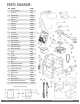
PARTS DIAGRAM: Item Description 1 Operator Cover Bolt (2) VASWCB 2 Operator Cover VNXF1CV 3 Output Shaft Knob DWOUK10 4 Output Shaft Cover VNXSWOSC 5 Clutch Key VAWRCK20 6 Clutch and Handle DWCL20 7 Output Arm DWAR20 8 Output Shaft DWOP20 9 Control Board VFLEXPCB 10 Fuse - 15 amp VNXF15A 11 Fuse - 4 amp VNXF4A 12 Limit Switch Holder DWLH10 13 Limit Switch (2) DULS10 14 Limit Cam & Holder DWLC10 15 Worm Gear #70 10:1 DWGB70 16 41B30 3/4 Sprocket (Gear) VASP3034
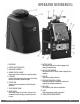
OPERATOR REFERENCES: 1. COVER BOLTS 2. OUTPUT SHAFT COVER (HAT) 3. MAIN COVER ASSEMBLY 4. MANUAL RELEASE HANDLE releases the clutch to allow for manual operation 9. BATTERY SWITCH disconnects batteries from the charging circuit during troubleshooting 10. MAIN AC POWER SWITCH discontinues the 115/230VAC power supplied to the operator FUSE 5. CLUTCH KEY 11.
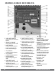
CONTROL BOARD REFERENCES: 1. POWER HARNESS CONNECTOR provides power to the control board. pg 18-19 2. “OPEN LEFT” & “OPEN RIGHT” provides power to the motor. pg 20 3. LIMIT SETUP BUTTONS available for future developments. 4. FEATURE ACTIVATION TRIM POTS activate and set features. pg 24 5. “EPS1” CONNECTOR available for future developments. 6. “EPS2” CONNECTOR available for future developments. 7. EMI BOARD CONNECTOR monitors the high voltage power supply. 8.
TABLE OF CONTENTS: PARTS DIAGRAM/PARTS LIST OPERATOR REFERENCES CONTROL BOARD REFERENCES IMPORTANT SAFETY INFORMATION Important Safety Instructions Important Installation Instructions Maintenance General Safety Precautions Operator Classification Photo Beam (non-contact sensor) Installation Edge Sensor (contact sensor) Installation Manual Release Audible Alarm Reset Installation Warning Placard Installation IMPORTANT INSTALLATION INFORMATION Specifications GATE OPERATOR INSTALLATION Concrete Pad Option (B
IMPORTANT SAFETY INFORMATION ! WARNING! Not Following these instructions may cause severe injury or death. IMPORTANT SAFETY INSTRUCTIONS ! WARNING! To reduce the risk of severe injury or death. 1. READ AND FOLLOW ALL INSTRUCTIONS . 2. Never let children operate or play with gate controls. Keep the remote away from children. 3. Always keep people and objects away from the gate. NO ONE SHOULD CROSS THE PATH OF THE MOVING GATE. 4. Test the gate operator monthly.
IMPORTANT SAFETY INFORMATION ! WARNING! Not Following these instructions may cause severe injury or death. IMPORTANT INSTALLATION INSTRUCTIONS (Continued) 6. Controls intended for user activation must be located at least six feet (6’) away from any moving part of the gate and where the user is prevented from reaching over, under, around or through the gate to operate the controls. Exception: Emergency access controls only accessible by authorized personnel (i.e.
IMPORTANT SAFETY INFORMATION ! WARNING! Not Following these instructions may cause severe injury or death. MAINTENANCE Remove the Power Harness from the Control Board. (refer to page 18) • Clean and lubricate the turning pins and gate hinges using the recommended lubricant. • Check that all hardware of the gate operator is properly tighten. • Ensure that the gate moves freely. • Check for corroded parts and replace if necessary.
IMPORTANT SAFETY INFORMATION ! CAUTION: To Reduce the Risk of Fire or Injury to Persons: a. Use only the following type and size battery(ies): Yuasa NP7-12 or VIKING DUBA12 b. Do not dispose of the battery(ies) in fire. The cells may explode. Check with local codes for possible disposal instructions. c. Do not open or mutilate the battery(ies). Released electrolyte is corrosive and may cause damage to the eyes or skin. It may be toxic if swallowed. d.
IMPORTANT SAFETY INFORMATION ! WARNING! Not Following these instructions may cause severe injury or death. NOTE: This type on installation does not reverse the gate all the way back to its limits when the photo beam is obstructed. This installation is only to protect against entrapment and to comply with UL325. Secondary Entrapment Protection Photo Beam (non-contact sensor) Installation • Photo beams or like must be installed to reduce the risk of entrapment.
IMPORTANT SAFETY INFORMATION ! WARNING! Not Following these instructions may cause severe injury or death. NOTE: This type on installation does not reverse the gate all the way back to its limits when the edge sensor is obstructed. This installation is only to protect against entrapment and to comply with UL325. Secondary Entrapment Protection Edge Sensor (contact sensor) Installation • Edge Sensors or like must be installed to reduce the risk of entrapment.
IMPORTANT SAFETY INFORMATION ! WARNING! Not Following these instructions may cause severe injury or death. Audible Alarm Reset Switch Installation Manual Reset for the Audible Alarm • UL325 standard requires an audible alarm to sound after two consecutive events detected by the primary entrapment protection of the gate operator (obstruction sensor). • The audible alarm will continue to sound for 5 minutes or until a stop command gets actuated. • The Stop command can be actuated in two different forms: 1.
IMPORTANT INSTALLATION INFORMATION ! CAUTION: To Reduce the Risk of Fire or Injury to Persons: ! WARNING: For use with gates at a maximum 1500 lbs. in weight or 16 ft. in length. DO NOT allow pedestrian use of this gate DO NOT install the gate operator to lift gates Locate Control Buttons: 1. Within sight of the gate, 2. At a minimum height of 5 feet so small children are not able to reach it; and 3. At least 6 feet away from all moving parts of the gate. 16 ft. 1000 lb. 12 ft. 1500 lb.
GATE OPERATOR INSTALLATION Concrete Pad Option 1. Follow the local building code to determine the required depth of the concrete pad. 2. Pad measurements recommended by Viking Access Systems are at least 23” long, 20” wide and 30” deep to ensure the stable operation of the operator, and a minimum of 6” above level grade to avoid any flooding of the machinery. 3.
GATE OPERATOR INSTALLATION Post Mounting Option TIP: The operator can be post mounted to be elevated above snow and flood lines. 1. Consult the local building codes for the depth and concrete requirements. 2. Maximum 3.00” OD pipe. 3. Provide a suf ficient number of conduit pathways for all low power accessories. Also provide conduit for the power supply to the operator. ! DO NOT run low voltage and high voltage wiring in the same conduit.
GATE OPERATOR INSTALLATION Operator Positioning ! IMPORTANT: Swing Gates must not open into public access areas. The gate must be installed in a location so that enough clearance is supplied between the gate, while opening and closing, and adjacent structures to reduce the risk of entrapment. ! TECHNICAL TIPS: Operator and Arm Geometry • Increasing “C” dimension provides better gate control and stability by reducing the effects of inertia and deceasing the gate leverage against the operator.
GATE OPERATOR INSTALLATION ! IMPORTANT: When attaching the Arm Assembly to the gate, if the “Gate Bracket” is not welded to a frame member that runs the full length of the gate, the operator may damage the gate. Do not attach the Gate Bracket to only a few pickets. STEP 1 STEP 2 Install the Clutch and cut the Arm Assembly to achieve the desired dimensions for “D” and “E” according to the formulas provided on page 16. With the gate at the closed, install the Arm Assembly.
ELECTRICAL INSTALLATION High Voltage Supply Option ! Caution: Always turn off power breakers when working with high voltage. DO NOT connect the “Power Harness” to the Control Board until the electrical installation is complete and ready for verification. STEP 1 At the “Power Box”: a. Set the “Voltage Selector” according to the supply voltage (115V or 230V). 1b 1a b. Turn the “AC Power” switch ON STEP 2 ! WARNING: SINGLE PHASE AC ONLY At the “J-Box”: a.
ELECTRICAL INSTALLATION Low Voltage Supply Option TIP: The operator is equipped with a Modular Power Box that can be relocated to provide power for low voltage installations. Supplies 24VAC to the operator. ! Caution: Always turn off power breakers when working with high voltage. DO NOT connect the “Power Harness” to the Control Board until the electrical installation is complete and ready for verification.
LIMITS SETUP STEP 1 Connect the “Limit Switch Harness” to the Control Board. a. “OPEN RIGHT” Connector if the gate opens Right. b. “OPEN LEFT” Connector if the gate opens Left. 1 1a 1b STEP 2 At the “Limit Cam & Holder” assembly: a. Loosen screws on both of the “Limit Switch Cams”. b. With the Articulating Arm and “Clutch” installed, insure that the “Clutch Guide Pin” is seated into one of the four holes on the “Cam Holder”. c.
LIMITS SETUP ! IMPORTANT: This gate operator uses mechanical limit switches. Therefore, the limits cannot be set electronically by the control board. The Limit Buttons on the control board have been rendered inactive. ! TECHNICAL TIP: Each Limit LED will illuminate solid when the corresponding limit switch is actuated. The LEDs will flash simultaneously while both limit switches are actuated at the same time. This display may indicate a problem with the limit switches or wires.
MASTER/SLAVE SETUP Two Wire Communication ! IMPORTANT: DO NOT run the Master/Slave communication cable in the same conduit or within 12” of 115 - 230v power supply cables. ! Technical Tip: DO NOT set the “Timer” and/or “Overlap” features on both operators Control Boards. Only turn these features on at the Master Control Board.
MASTER/SLAVE SETUP Wireless Communication Options ! Technical Tip: DO NOT set the “Timer” and/or “Overlap” features on both operators Control Boards. Only turn these features on at the Master Control Board. REQUIRED ADD-ON: Choose option A or B A. Viking Konnect - Wireless Master/Slave Kit PART# VA-KONNECT-MS B. Viking Blue - Wireless Master/Slave Kit PART# VA-BLUE-MSKT Connect the Modules provided to the “V.K” plug & play connection of each operators Control Board.
CONTROL BOARD SETUP Initial Settings “Timer” Hold Open Timer “Overlap” Overlap Delay Automatically closes the gate after the selected amount of time from 1-60 seconds. For Master/Slave applications. The control board that has this feature turned on is the MASTER and will delay from 1-6 seconds. Slave will delay to close. Turning the dial between “0” and “OFF” will disable this feature, requiring a close command to close the gate. ! Do not turn this feature on at both control boards, only the Master.
CONTROL BOARD SETUP Initial Settings NOTE: Installing a shunt or jumper on the pins will activate the feature. “Auto Open” - Power Failure Option Opens the gate automatically during power failure. Resumes normal operation when power is restored. “Last Open” - Power Failure Option Opens the gate automatically when the battery backup voltage is critically low. “Fail Safe/Secure” During complete power failure, including battery power; determines the force required to manually move the gate.
CONTROL BOARD SETUP Obstruction Sensor (Primary Entrapment Protection) ! IMPORTANT: The appropriate “ODS” setting is dependant upon the gate installation and construction. Set this feature accordingly. Additional Safety equipment should be used to reduce possible risk of injury or vehicle damage. “ODS” Obstruction Detection Sensor The Obstruction Sensor detects obstructions in the path of the traveling gate.
CONTROL BOARD SETUP Viking Heater The operator has an integrated heater that is thermostatically controlled. Activate this feature when the operator is used in application temperatures down to -20°F (-29°C). To set the heater to turn on at the Close Limit: 1. Use the “Diagnose” button to scroll through the LCD Display to “HEATER CLS” 2. Press and hold the “Stop” button on the control board. 3. Press and release the “Diagnose” button to turn this feature ON and OFF.
(THIS PAGE LEFT BLANK INTENTIONALLY) 28 VIKING TECHNICAL SUPPORT 1.800.908.
ACCESSORY CONNECTIONS Re-Open Photo Beam (vehicular Safety) NOTE: This type of photo-beam installation will stop then RE-OPEN the gate all the way to the open limit when the beam is obstructed. Intended for vehicular safety ONLY. For the purpose of pedestrian entrapment, see pages 10-11. N.O. COM (-) (+) Note regarding Photo Beam types: Check for proper operation: Fail-Safe type - connect the “N.C.” terminal of the photo beam to the “Re-Open” terminal on the control board.
ACCESSORY CONNECTIONS Radio Receiver (Typical) ! IMPORTANT: The Hold Open “Timer” setting (page 24) affects how the gate will respond to the radio receiver command. The control board provides two modes of operation that a radio receiver can control the gate: Open-Stop-Close 1. By having the radio receiver connected as illustrated and with the Hold Open Timer OFF (see page 24): COM N.O. (-) (+) Every command of the radio transmitter will control the gate as follows: a. First command opens the gate, b.
ACCESSORY CONNECTIONS Anti-Tailgate, Open Commands & Guard Station ! TECHNICAL TIP: For more information regarding accessory connections and terminal functions, refer to “Appendix (A)” on pages 42-43. Open Commands “Exit ”, “Fire” and “Strike” input terminals all provide an open command to the control board. Any device connected as shown will open the gate. + + - + - N.O. COM N.O. COM N.O. COM Guard Station ! All three buttons must be a Normally Open “N.O.
ACCESSORY CONNECTIONS Viking Loop Rack TIP: This operator may be equipped with a pre-wired Loop Rack that plug-in type loop detectors can be connected to. This provides a convenient alternative to the box type loop detectors that would need to be wired to the control board. Viking does not provide either type of loop detectors. 32 Loop Rack: Part # VA-LR Loop Rack Wiring Harness: Part # VA-LRH VIKING TECHNICAL SUPPORT 1.800.908.
ACCESSORY CONNECTIONS Guidelines for Loop Installation 1. Prevent sharp corners in the geometry of the loop sensor. 2. Install the appropriate number of turns for your loop geometry based on the loop perimeter. Use Table C (below) as a guide. 3. Use XLP (cross-linked-polyethylene) type of wire. This wire reduces the effects of moisture and other environmental events in altering the functionality of the vehicular loop detector. 4. Twist the lead wire at least 6 turns per foot. 5.
ACCESSORY CONNECTIONS Magnetic Lock, Lock Solenoid NOTE: Viking Access Systems does not provide external gate lock devices. These items can be purchased from your dealer or distributor. Power for the Locks: Magnetic Lock Do not use the 24VDC power supplied by the control board. An external power supply, or plug-in transformer, must be used for the magnetic lock or lock solenoid. Plug the transformer into the “120VAC” receptacle provided at the operators Power Box.
SYNCHRONIZATION WITH B-12 Barrier Arm (B-12) Synchronization Option NOTE: The Control Board provides a convenient solution for applications that require synchronized operation with the Viking Barrier Arm Operator model B-12. This type of application opens and closes in the following pattern: 1. Open Command is provided only to the Viking B-12 Barrier Arm Operator. 2. The Barrier Arm will delay to open until this Gate Operator reaches its Open Limit. 3.
TROUBLESHOOTING LED References In addition to the LCD Display, the control board LEDs monitor the various circuits of the control board. Use the table below to identify the corresponding “TS Ref#” and refer to page 38-41 for further troubleshooting. Page 41 TS Ref#(s) # LED Status Meaning 1 OFF At Closed Limit and Magnetic Lock Relay state is closed across “COM” & “N.C”. (pg 34). Gate should be at the Close Limit. SOLID Not at Closed Limit and Magnetic Lock Relay state is closed across “COM” & “N.
TROUBLESHOOTING LED References Use the table below to identify the corresponding “TS Ref#” and refer to page 38-41 for further troubleshooting. Pg 41 # LED Status Meaning 9 OFF Normal Condition. SOLID Control Board is receiving an input from a device connected to the C Loop terminal (pg 32, 42). OFF Normal Condition. SOLID Control board is receiving an input from a device connected to any of the following input terminals: Exit, Fire, Strike or Open (pg 31, 42). OFF Normal Condition.
TROUBLESHOOTING LCD Display References The control board is equipped with a LCD Display that provides operator information, current conditions, settings, diagnostics and error messages. Use the table below to identify the corresponding “TS Ref#” and refer to page 41 for further troubleshooting. 1. Error Messages will be displayed first. 2. The ”Diagnose” LED will flash consecutively indicating how many Error Messages are available. 3.
TROUBLESHOOTING LCD Display References LCD MSG Meaning Multi Meter Displays MOT AMP __._ A MOT VOLT __._ VDC AC VOLT __._ VAC CHARGE __._ VDC BAT VOLT __._ VDC Page 41 TS Ref #s This is the motor current amperage during operation This is the actual motor voltage during operation This is the actual low voltage AC to the Control Board from the transformer Indicates the charging voltage to the batteries, if the Battery Switch is in the OFF position.
TROUBLESHOOTING LCD Display References Page 37 TS Ref #s LCD MSG Meaning Error Messages ERR AC LOW ERR AC HIGH ERR AC NO AC ERR CHRG HIGH ERR CHRG CHECK 4A ERR BAT LOW ERR FUSE 15 AMP ERR EMI NO EMI ERR EMI NO FUSE ERR EMI NO AC ERR EMI Unknown ERR EMI PROTECT 40 Indicates that the 24VAC supply to the VFlex Board is too low from the 115/230 power supply. 1, 3, 20 Indicates that the 24VAC supply to the VFlex Board is too high from the 115/230 power supply.
TROUBLESHOOTING Solutions Begin the troubleshooting process by referring to the error messages on the LCD Display and/or the Status LEDs on the control board. Use pages 36-40 to identify the Troubleshooting Reference # (TS Ref#) then reference the table below. TS Ref# CHECK 1 Page Ref# Check that the high voltage power supplied to “EMI Board” is within range. 100V-120V or 200V-240V pg 18 2 Remove and check EMI Fuse for continuity.
Appendix (A) Access Control Connections Power Connections The control board provides a 24VDC output to power external devices and controls. Alternatively, for devices that require a power supply other than 24VDC , the operators Power Box contains a convenient 120VAC receptacle to connect a plug-in transformer. Terminals Connections and Input Functions: Viking Terminal “+28V” “GND” “GND” “Radio” Function “C” “N.O.
APPENDIX (A) Relays In General NOTE: Viking Access Systems does not provide the external safety devices and access controls. These items can be purchases from your dealer or distributor. In General Glossary of Terms In regards to the Viking control board, all external safety devices and access controls contain, and are, simple relays that provide an input to the Viking control board when the device is activated. 1. Terminal: Wire Connections. 2.
Appendix (B) Common Radio Receivers - Connections 44 VIKING TECHNICAL SUPPORT 1.800.908.
APPENDIX (C) Solar Applications NOTE: Viking recommends Solar Package (part # VA-SOCHP) for most general solar applications. Alternatively, individual and third party solar components can be used. The following are minimum system requirements and installation information. Panels • Voltage 24V • Wattage 80W (minimum) Cut the wires coming from the toroidal transformer. Connect the solar panel cables to the power harness as shown.
VIKING EXPANSION PRODUCTS VIKING KONNECT Master/Slave Kit Secure and reliable Master/Slave communication using Viking’s Konnect technology. Paired with the Viking App, each module also doubles as a diagnostic tool. Part# VA-KONNECT-MS ***Q -7, B-12 & ECU Operators require (2) Antenna Extension Cables (part# VA- RPSMA)*** VIKING KONNECT Diagnostic Tool On-site remote access to the operator from the convenience of a compatible hand held device.
OUR CONTINUOUS COMMITMENT TO EXCELLENCE Viking Access Systems is continuously working hard to identify and design products that will appeal to the industry and its needs. As technology continues to advance, we have developed a completely efficient and intelligent line of gate operators to meet the changing demands. These machines offer: full UL325 and UL991 compliance, soft-start and soft-stop, intelligent obstruction sensors, continuous operation (100% duty cycle) and extreme power efficiency.
STANDARD FEATURES AND OPERATOR SPECIFICATIONS • UL Listed; UL325 and UL991 • Intelligent speed control with smooth start and stop, self-adjust system • ETL Listed; UL325 and UL991 • Fail-Safe option sets the gate to automatically transfer to a fail-safe mode in the event of a power failure, allowing the gate to be pushed open without the use of special knowledge of the equipment • Fail-Secure option sets the gate to electronically lock in the event of a power failure, allowing no manual movement without t