
Instruction Manual
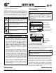
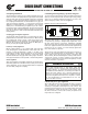

5. Concrete foundation
If a concrete foundation is used, allow the concrete to set
mSNMZCFGPSFCPMUJOHEPXOUIFHFBSESJWF(SPVUTUSVDUVSBM
TUFFM NPVOUJOH QBET BOE CPMUT PG TVGmDJFOU TJ[F JOUP UIF
concrete, to adequately distribute the load stress onto the
concrete foundation.
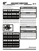
Figure 1: Concrete Foundation
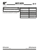
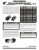
6. Bolt connections for footed & flange mounted units
/03%GPPUFESFEVDFSTBOEnBOHFNPVOUSFEVDFSTXJUI#
nBOHFIBWFDMFBSBODFEFTJHOFEJOUPUIFNPVOUJOHIPMFTUP
BMMPX GPS TPNF NJOPS BEKVTUNFOUT JO BMJHONFOU #P*U TJ[F
TUSFOHUI BOE RVBOUJUZ TIPVME CF WFSJmFE UP JOTVSF QSPQFS
torque reaction capacity whatever the mounting arrange-
ment. Tightening torque for gear reducer mounting bolts,
and recommended fastener grades, are provided in Table 2.
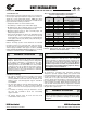
Table 2A: Tightening Torque for Inch Reducer Mounting Bolts
Thread
Size
Tightening Torque
Grade SAE 5 /
ASTM A449
Grade SAE 8
(in) (lb-in) (lb-ft) (Nm) (lb-in) (lb-ft) (Nm)
1/4-20 85 7.1 9.6 120 10.0 13.6
5/16-18 190 16 21 267 22 30
3/8-16 330 28 37 470 39 53
1/2-13 825 69 93 1,170 98 132
5/8-11 1,660 138 188 2,340 195 264
3/4-10 2,960 247 334 4,180 348 472
7/8-9 4,750 396 537 6,700 558 757
1-8 7,100 592 802 10,000 833 1,130
1 1/8-7 -
- -
14,800 1,233 1,672
1 1/4-7
- - -
20,600 1,717 2,327
1 3/8-6
- - -
27,200 2,267 3,073
1 1/2-6
- - -
35,800 2,983 4,045
1 3/4-5
- - -
53,500 4,458 6,045
t $BMDVMBUFE UJHIUFOJOH UPSRVFT BSF CBTFE B DPOWFOUJPOBM
60°, clean and dry (un-lubricated) thread, with thread-
friction and head-friction equal to 0.15.
t 8IFOVTJOHJODIGBTUFOFST/03%SFDPNNFOETBNJOJNVN
(SBEF 4"& "45. " GPS TJ[FT VQ UP 6/$ BOE
(SBEF4"&GPSBMMMBSHFSTJ[FT
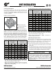
Table 2B: Tightening Torque for Metric Reducer Mounting Bolts
Above Tightening Torque
ISO Grade 8.8 ISO Grade 10.9
(mm) (lb-in) (lb-ft) (Nm) (lb-in) (lb-ft) (Nm)
. 28 2.4 3.2 42 3.5 4.7
. 57 4.7 6.4 82 6.9 9.3
. 97 8 11 142 12 16
. 239 20 27 345 29 39
. 469 39 53 690 58 78
. 814 68 92 1,195 100 135
. 1,283 107 145 1,903 159 215
. 2,036 170 230 2,965 247 335
. 2,036 170 230 2,965 247 335
. 4,071 339 460 5,841 487 660
. 5,576 465 630 7,966 664 900
. 6,992 583 790 10,178 848 1,150
. 10,178 848 1,150 14,604 1,217 1,650
. 14,161 1,180 1,600 19,914 1,660 2,250
. 24,605 2,050 2,780 34,606 2,884 3,910
. 39,563 3,297 4,470 55,671 4,639 6,290
t $BMDVMBUFEUJHIUFOJOHUPSRVFTBSFCBTFEPOBDPOWFOUJPOBM
60°, clean and dry (un-lubricated) thread, with thread-
friction and head-friction equal to 0.15.
t 8IFO VTJOH NFUSJDGBTUFOFST /03% SFDPNNFOET B
minimum ISO Grade 8.8 bolt.
7. Mounting the prime mover
8IFOUIFNPUPSJTOPUnBOHFNPVOUFEPSJOUFHSBMMZNPVOUFE
to the gearbox, it is important to properly secure and
align the gear drive with respect to the driven machine
before attempting to align the prime mover or motor.
" "GUFSUIFNBJOHFBSESJWFJTQSPQFSMZBMJHOFEBOECPMUFEJO
place, align the prime mover with respect to the reducer
input shaft.
# 6TFTIJNTVOEFSUIFGFFUPGUIFQSJNFNPWFSBTOFFEFE
and secure in place with the proper mounting bolts. Dowel
QJOTNBZCFmFMEJOTUBMMFEUPIFMQQSFWFOUNJTBMJHONFOU
and ensure proper realignment if removed for service.
IMPORTANT NOTE
8IFOVTJOHBIJHITQFFEDPVQMJOHDPOOFDUJPOCFUXFFO
the prime mover and the reducer, check alignment
per the coupling manufacturers recommendations. If
the coupling is misaligned, the reducer alignment or
shimming is incorrect. Re-align the gear reducer and
re-check the high-speed coupling alignment before re-
aligning the motor.
DRIVESYSTEMS
UNIT INSTALLATION
RETAIN FOR FUTURE USE
U10060 - 2 of 2
! Grouted Structural
4UFFM.PVOUJOH1BET
" .PVOUJOH#PMUT
# Concrete Foundation
www.nord.com/docs06.09.09
NORD Gear Corporation
Toll Free in the United States: 888.314.6673
NORD Gear Limited
Toll Free in Canada: 800.668.4378