
Manual


SECTION TSM 110.2 ISSUE C PAGE 4 OF 6
〇
〇
〇
〇
〇
〇
〇
〇
〇
〇
〇
〇 〇
〇
〇
〇
〇 〇
〇
〇
〇
〇
〇
〇
〇
〇
〇
〇
〇
〇
〇
〇
〇
〇
1
2
3
4
5
6
7
8
9
10
11
12
13
4
14
15
16
17
18
19
20
21
22
23
24
25 26
27
28
29
30
31
32
21
DISASSEMBLY
1. Mark head and casing before disassembly to insure proper
reassembly. The idler pin, which is offset in pump head,
must be positioned toward and equal distance between
port connections to allow for proper flow of liquid through
the pump.
Remove head from pump. Do not allow idler to fall from
idler pin. Tilt top of head back when removing to prevent
this. Avoid damaging head gasket.
2. Remove idler and bushing assembly
3. Insert length of hardwood or brass through port opening
between rotor teeth to keep shaft from turning. Bend up
tang of lockwasher and with a spanner wrench, remove
locknut and lockwasher from shaft.
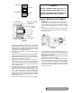
4. Loosen two setscrews in the face of the bearing housing
and remove the bearing housing assembly from the
bracket. Refer to Figure 5.
5. Remove pair of half round rings under the inner spacer
collar from the shaft.
6. Remove packing gland capscrews, slide packing gland
out of stuffing box, remove packing and lantern ring.
7. Carefully remove rotor and shaft to avoid damaging
bracket bushing.
8. Loosen two radial setscrews in flange of bearing housing
and with a spanner wrench remove the outer end cap
with lipseal and outer bearing spacer collar.
9. Remove the double row ball bearing, lipseal and inner
bearing spacer collar from the bearing housing.
10. Clean all parts thoroughly and examine for wear and
damage. Check lip seals, ball bearing, bushings and idler
pin and replace if necessary. Check all other parts for
nicks, burrs, excessive wear and replace if necessary.
Wash bearings in clean solvent. Blow out bearings with
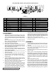
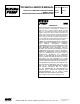
ExPLODED VIEW - MODEL LV3900 (FOR PARTS IDENTIFICATION)
ITEM NAME OF PART ITEM NAME OF PART ITEM NAME OF PART
1 Locknut 13 Packing 25 Pipe Flange Gasket
2 Lockwasher 14 Lantern Ring 26 Idler, Idler Disc, and Lipseal
3 End Cap for Bearing Housing 15 Packing Retainer Washer 27 Idler Bushing
4 Lipseal for Bearing Housing 16 Bracket Bushing 28 Head Gasket
5 Bearing Spacer Collar (Outer) 17 Pressure Relief Plug 29 Idler Pin
6 Ball Bearing 18 Grease Fittings 30 Head and Idler Pin
7 Bearing Spacer Collar (Inner) 19 Bracket and Bushing 31 Capscrew for Head
8 Ring, Half Round 20 Capscrew for Bracket 32 Grease Fitting
9 Bearing Housing 21 Pipe Plug
10 Packing Gland 22 Back Flange Gasket
11 Packing Gland Nut 23 Nut
12 Packing Gland Capscrew 24 Studs
ASSEMBLY
1. Install bracket bushing. If bracket bushing has a lubrication
groove, install bushing with groove at 6–o’clock position
in bracket.
2. Coat shaft of rotor shaft assembly with light oil. Start
end of shaft in bracket bushing turning from right to left,
slowly pushing rotor in casing.
3. Coat idler pin with light oil and place idler and bushing on
idler pin in head.
4. Using a .010 to .015 inch head gasket, install head and
idler assembly on pump. Pump head and casing were
marked before disassembly to insure proper reassembly.
If not, be sure idler pin, which is offset in pump head,
is positioned toward the equal distance between port
connections to allow for proper flow of liquid through
pump.
Tighten head capscrews evenly.
5. When assembling packed pump, use packing suitable
for liquid being pumped. Install packing, staggering the
joints from one side of shaft to other. Lubricate packing
rings with oil, grease, or graphite to aid assembly. NOTE:
Be sure the lantern ring is positioned below the grease
fitting. Install and seat each ring of packing one at a time,
staggering the ring joints from one side of the shaft to
the other. Lubricate the packing rings with oil, grease or
compressed air. Do not allow bearings to spin; turn them
slowly by hand. Spinning bearings will damage race and
balls. Make sure bearings are clean, then lubricate with
light oil and check for roughness. Roughness can be
determined by turning outer race by hand.
11. Casing can be checked for wear or damage while
mounted on bracket.
FIGURE 2