
Manual


SECTION TSM 110.2 ISSUE C PAGE 5 OF 6
graphite to aid assembly. A length of pipe or tubing will
help to install and seat each packing ring. Install packing
gland, capscrews, and nuts. Make sure gland is installed
square and nuts are tightened evenly. Tighten nuts until
packing gland is snug against packing.
6. Slide the inner spacer collar over the shaft with recessed
end facing rotor.
7. Install the lip seal (lip toward end of shaft) in the bearing
housing and turn the bearing housing into the bracket.
8. Pack the ball bearing with grease, place on the shaft and
push or drive into place in the housing.
9. Install the lip seal (with lip toward end of shaft) and
bearing spacer collar in the outer end cap and turn the
end cap into the bearing housing until tight against the
bearing. Lock in place with two set screws in the flange
of the bearing housing.
10. Put lockwasher and locknut on shaft. Insert length of
hardwood or brass through port opening between rotor
teeth to keep shaft from turning. Tighten locknut to 100-
130 Ft. - lbs. Torque. Bend one tang of lockwasher into
slot of locknut. If tang does not line up with slot, tighten
locknut until it does. Failure to tighten locknut or engage
lockwasher tang could result in early bearing failure and
cause damage to pump.
Remove length of hardwood or brass from port opening.
3. Tighten the two self locking type “Allen” set screws “A” in
the outboard face of the bearing housing with equal force
against the bracket. Your pump is now set with standard
end clearances and locked.
NOTE: Be sure the shaft can rotate freely. If not, back off
additional notches and check again.
4. High viscosity liquids require additional end clearances.
The amount of extra end clearance depends on the amount
of the liquid pumped. For specific recommendations,
consult the factory. Each additional ¼” on the outside
diameter of the bearing housing is equivalent to an extra
end clearance of .001”.
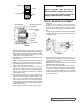
FIGURE 5
FIGURE 4
BALL BEARING
SETSCREW
BEARING HOUSING
SPACER COLLAR
SHAFT
CLOSURE
ENDCAP
SETSCREW
HALF ROUND RINGS
BUSHING
LIPSEAL
IDLER
IDLER DISC
FIGURE 3
THRUST BEARING ADJUSTMENT
See Fig. 5
1. Loosen the two set screws “A” in the outer face of the
bearing housing “B” clockwise until it cannot longer be
turned by hand. Back off counter clockwise until the
rotor shaft can be turned by hand with a slight noticeable
drag.
2. For standard end clearance, back off the thrust bearing
assembly “B” 1.25” length measured on the outside of
the bearing housing.
DANGER
BEFORE STARTING PUMP, BE SURE ALL
DRIVE EQUIPMENT GUARDS ARE IN PLACE.
FAILURE TO PROPERLY MOUNT GUARDS MAY
RESULT IN SERIOUS INJURY OR DEATH.