
Manual

SECTION TSM 141.2 ISSUE F PAGE 10 OF 12
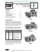
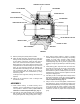
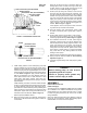
FIGURE 11
TAPERED INSTALLATION SLEEVE
SHAFT
MECHANICAL SEAL
ROTARY MEMBER
GREASE FITTING
SETSCREWS
OUTER END CAP
LOCKWASHER
LOCKNUT
OUTER
SPACER
COLLAR
OUTER LIP
SEAL
BRACKET
BALL BEARING
INNER
LIP SEAL
INNER SPACER
COLLAR
HALF
ROUND
RINGS
INNER
END CAP
NYLON INSERT
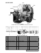
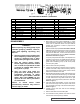
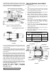
FIGURE 13
LEFT SIDE
OF PUMP
SEAL ACCESS HOLE (FOR SETSCREWS)
MECHANICAL SEAL (ROTARY MEMBER)
SEAL SEAT
SEAL HOLDER
SEAL SEAT GASKET
SEAL
HOLDER
PLATE
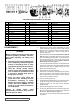
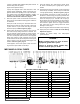
TOTAL END CLEARANCE CHART
PUMP
SIZE
TURN OUTER END CAP
COUNTER-CLOCKWISE
NO. OF NOTCHES
TOTAL
END
CLEARANCE
LS 2.5 .005
Q, QS AND M 5 .010
A tapered sleeve is available, at extra cost, for Q, QS and M
pumps from Viking Pump for seal installation on shaft. LS size
pump shaft is tapered and installation sleeve is not available.
Place tapered sleeve on shaft, Refer to Figure 11.
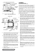
FIGURE 10 - OPTIONAL MECHANICAL SEAL
Never touch sealing faces with anything except clean hands
or clean cloth. Minute particles can scratch the seal faces
and cause leakage.
Coat tapered sleeve and inside of the rotary member with
a generous quantity of SAE 30 non-detergent oil. Grease is
not recommended. Start rotary member on shaft and over
tapered sleeve.
Move rotary member so setscrews are directly below seal
access holes on left side of bracket (viewed from shaft end)
Refer to Figure 10. Tighten all setscrews securely to shaft.
Flush sealing faces of both rotary member and seal seat with
oil and install seal seat and seat gasket over end of shaft
against machined bracket face. Assemble other seal seat
gasket, seal holder, seal holder plate, capscrews and nuts
and tighten securely. Remove tapered installation sleeve.
Some PTFE seals are equipped with holding clips which
compress the seal springs. Remove holding clips to release
springs after seal is installed on shaft.
AT THIS POINT, FINISH ASSEMBLY PROCEDURES
STARTING AT STEP 8, PAGE 9 (STANDARD
MECHANICAL SEAL).
1. Loosen two setscrews over each outer and inner end
caps.
2. Turn inner end cap clockwise (viewed from shaft end)
until it projects slightly into opening on side of bracket
exposing approximately three threads.
3. Turn outer end cap clockwise until rotor is tight against
head and rotor shaft cannot be turned.
4. Make a reference mark on bracket end, opposite a
notch on outer end cap. Back off outer end cap required
number of notches as shown in Total End Clearance
Chart. Refer to Figure 11. Each notch represents .002”
end clearance.
5. High viscosity liquids require additional end clearances.
The amount of extra end clearance depends on
the viscosity of the liquid pumped. For specific
recommendations contact factory.
6. Tighten inner end cap with a spanner wrench. Tap
spanner wrench lightly but DO NOT OVER-TIGHTEN as
it will damage threads.
7. Tighten set screws that hold inner and outer end caps to
prevent their turning in bracket.
8. Check rotor to determine if it turns freely; if it does not,
add more end clearance.
THRUST BEARING ADJUSTMENT
Refer to Figure 13