
Manual

SECTION TSM 141.2 ISSUE F PAGE 5 OF 12
ASSEMBLY
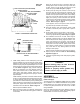
1. Install bracket bushing. If bracket bushing has a
lubrication groove, install bushing with groove at 6:00
o’clock position in bracket. If carbon graphite, Refer to
Installation of Carbon Graphite Bushings, page 11.
2. Coat shaft of rotor shaft assembly with non-detergent
SAE 30 weight oil. Start end of shaft in bracket bushing
turning from right to left, slowly pushing rotor in casing.
9. Remove packing and packing retainer washer.
10. Clean all parts thoroughly and examine for wear and
damage. Check lip seals, ball bearing, bushings and idler
pin and replace if necessary. Check all other parts for
nicks, burrs, excessive wear and replace if necessary.
Wash bearings in clean solvent. Blow out bearings with
compressed air. Do not allow bearings to spin; turn them
slowly by hand. Spinning bearings will damage race
and balls. Make sure bearings are clean, then lubricate
with non-detergent SAE 30 weight oil and check for
roughness. Roughness can be determined by turning
outer race by hand.
If bearings have roughness, bearings will need to be
replaced.
11. Casing can be checked for wear or damage while
mounted on bracket.
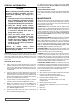
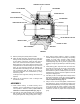
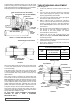
GREASE FITTING LOCATION
INNER SPACER COLLAR
OUTER SPACER COLLAR
LOCKWASHER
SETSCREWS
OUTER END CAP
LOCKNUT
INNER LIP SEAL
HALF ROUND RINGS
INNER END CAP
NYLON INSERT
SHAFT
BALL BEARING
BRACKET
OUTER LIP SEAL
3. Place packing retainer washer in bottom of packing
chamber and pack pump with new packing. Use packing
suitable for liquid being pumped. Install packing,
staggering the joints from one side of shaft to other.
Lubricate packing rings with oil, grease or graphite to aid
assembly. A length of pipe will help to seat each packing
ring.
4. Install packing gland, capscrews and nuts. Back rotor
and shaft out of casing just far enough to insert packing
gland through side opening of bracket over end of
shaft. Make sure gland is installed square and nuts are
tightened evenly. Tighten nuts wrench tight then back off
until gland is slightly loose.
5. Coat idler pin with non-detergent SAE 30 weight oil and
place idler and bushing on idler pin in head. If replacing
with carbon graphite bushing, Refer to Installation of
Carbon Graphite Bushings, page 11.
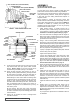
6. Using a .010 to .015 inch head gasket, install head and
idler assembly on pump. Pump head and casing were
marked before disassembly to insure proper reassembly.
If not, be sure idler pin, which is offset in pump head,
is positioned toward and equal distance between port
connections to allow for proper flow of liquid through
pump.
FIGURE 5