
Manual

SECTION TSM 141.2 ISSUE F PAGE 6 OF 12
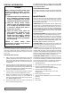
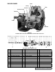
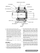
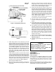
EXPLODED VIEW FOR MODEL LS4125
ITEM NAME OF PART ITEM NAME OF PART ITEM NAME OF PART
1 Locknut 14 Mechanical Seal 27 Rotor and Shaft
2 Lockwasher 15 Set Collar 28 Idler and Bushing
3 End Cap (Outer) 16 Grease Fitting 29 Idler Bushing
4 Lip Seal for End Cap 17 Pipe Plug 30 Head Gasket
5 Bearing Spacer Collar (Outer) 18 Bracket and Bushing 31 Idler Pin
6 Ball Bearing 19 Capscrew for Bracket 32 Head and Idler Pin
7 Bearing Spacer Collar (Inner) 20 Bracket Bushing 33 Gasket for Jacket Head Plate
8 Ring, Half Round 21 Bracket Gasket 34 Jacket Head Plate
9 End Cap (Inner) 22 Casing 35 Capscrew for Head
10 Nut for Seal Holder 23 Nut for Flanges 36 Relief Valve Gasket
11 Capscrew for Seal Plate 24 Capscrew for Flanges 37 Capscrew for Relief Valve
12 Seal Plate 25 Pipe Flange Gasket 38 Internal Relief Valve
13 Seal Holder 26 Pipe Plug 39 Cover Plate, Relief Valve
If pump is equipped with jacketed head plate, install at
this time along with new gasket.
Tighten head capscrews evenly.
If pump was equipped with a relief valve and it was
removed during disassembly, install on head with new
gaskets. Relief valve adjusting screw cap must always
point toward suction port. Refer to Figures 1, 2 and 3
on page 1. For relief valve repair or adjustments, Refer
to Pressure Relief Vavle Instructions, Page 11.
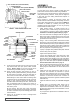
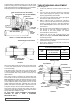
7. Slide inner spacer collar over shaft with recessed end
facing rotor. Q, QS and M size bearing spacer collars are
not recessed.
Place pair of half round rings on shaft and slide inner
bearing spacer collar over half round rings to lock them
in place. There is no pair of half round rings on Q, QS
and M size pumps. Refer to Figure 5, page 5.
8. Press lip seal, lip facing end of shaft, in inner end cap
and insert end cap through shaft end of bracket. Turn
end cap clockwise, looking at shaft end, until it engages
threads. End cap spanner wrench holes must be facing
rotor. Turn end cap with spanner wrench until it projects
slightly from opening on side of bracket. End cap must
not be turned so far that lip seal drops off end of spacer
collar on shaft or end cap becomes disengaged from
threads. Refer to Figure 5, page 5.
If this happens, remove inner spacer collar, half round
rings and end cap and start over at Step 7.
9. Pack ball bearing with multi-purpose grease, NLGI
#2. Place on shaft and push or gently drive in place in
bracket.
10. Press lip seal, lip facing end of shaft, in outer end cap and
insert end cap in bracket. Turn end cap in bracket until
it is tight against bearing. Refer to Figure 5, page 5.
11. Put Iockwasher and locknut on shaft. Insert length of
hardwood or brass through port opening between rotor
teeth to keep shaft from turning. Tighten locknut to 120-
150 ft.-lbs. Torque (LS) or 170-190 ft.-lbs. Torque (Q,
QS, M). Bend one tang of lockwasher into slot of locknut.
If tang does not line up with slot, tighten locknut until it
does. Failure to tighten locknut or engage lockwasher
tang could result in early bearing failure and cause
damage to rest of pump.
Remove length of hardwood or brass from port opening.
12. Adjust pump end clearance. Refer to Thrust Bearing
Adjustment, page 10.
13. Lubricate all grease fittings with multi-purpose
grease, NLGI #2.
DANGER !
Before starting pump, be sure all drive
equipment guards are in place.
Failure to properly mount guards may
result in serious injury or death.
MECHANICAL SEAL PUMPS