
Manual

SECTION TSM 141.2 ISSUE F PAGE 7 OF 12
1. Mark head and casing before disassembly to insure
proper reassembly. The idler pin, which is offset in pump
head, must be positioned toward and equal distance
between port connections to allow for proper flow of
liquid through pump.
Remove head from pump. Do not allow idler to fall from
idler pin. Tilt top of head back when removing to prevent
this. Avoid damaging head gasket. If pump is furnished
with pressure relief valve, it need not be removed from
head or disassembled at this point. Refer to Pressure
Relief Valve Instructions, page 11.
If LS pump has jacketed head plate, it will separate from
head when it is removed. The gasket between head and
jacket head plate must be totally removed. Use new
gasket when assembling pump. Q, QS and M pumps
have one piece gasket.
2. Remove idler and bushing assembly.
3. Insert length of hardwood or brass through port opening
between rotor teeth to keep shaft from turning. Bend up
tang of lockwasher and with a spanner wrench remove
locknut and lockwasher from shaft.
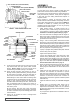
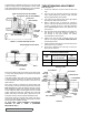
4. Standard Mechanical Seal (synthetic rubber bellows type)
uses a set collar behind the seal spring. Two setscrews
must be loosened before shaft can be removed. Access
to collar setscrews is through seal access hole on right
hand side of mounting bracket (viewed from shaft end,
Refer to Figure 6.)
5. Tap shaft forward approximately 0.5 inch and remove
pair of half round rings under inner spacer collar. There
is no pair of half round rings on Q, QS and M size pumps.
Refer to Figure 7.
6. Carefully remove rotor and shaft to avoid damaging
bracket bushing.
7. Remove seal holder and seal holder plate.
8. The seal seat and rotary member of the seal can now be
removed from the side opening of bracket.
DISASSEMBLY
DANGER !
Before opening any Viking pump liquid
chamber (pumping chamber, reservoir,
relief valve adjusting cap fitting, etc.)
Be sure:
1. That any pressure in the chamber has
been completely vented through the
suction or discharge lines or other
appropriate openings or connections.
2. That the driving means (motor,
turbine, engine, etc.) has been “locked
out” or made non-operational so that
it cannot be started while work is
being done on pump.
3. That you know what liquid the
pump has been handling and the
precautions necessary to safely
handle the liquid. Obtain a material
safety data sheet (MSDS) for the
liquid to be sure these precautions
are understood.
Failure to follow above listed
precautionary measures may result in
serious injury or death.
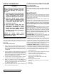
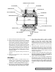
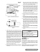
EXPLODED VIEW FOR MODELS Q, QS AND M125
ITEM NAME OF PART ITEM NAME OF PART ITEM NAME OF PART
1 Locknut 13 Set Collars 25 Rotor and Shaft
2 Lockwasher 14 Pipe Plug 26 Idler and Bushing
3 End Cap (Outer) 15 Grease Fitting 27 Idler Bushing
4 Lip Seal for End Cap 16 Bracket and Bushing 28 Head Gasket
5 Bearing Spacer Collar 17 Capscrew for Bracket 29 Idler Pin
6 Ball Bearing 18 Bracket Bushing 30 Head and Idler Pin
7 End Cap (Inner) 19 Bracket Gasket 31 Stud for Head
8 Nut for Seal Holder 20 Stud for Flanges 32 Nut for Head
9 Capscrew for Seal Holder 21 Nut for Flanges 33 Relief Valve Gasket
10 Seal Holder Plate 22 Casing (QS size has opposite ports) 34 Capscrew for Relief Valve
11 Seal Holder 23 Pipe Flange Gasket 35 Internal Relief Valve
12 Mechanical Seal 24 Pipe Plug Suckback Line, Not Illustrated