
Manual

SECTION TSM 141.2 ISSUE F PAGE 8 OF 12
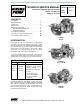
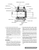
GREASE FITTING
SETSCREWS
OUTER END CAP
LOCKWASHER
LOCKNUT
OUTER
SPACER
COLLAR
OUTER LIP
SEAL
BRACKET
BALL BEARING
INNER
LIP SEAL
INNER SPACER
COLLAR
HALF
ROUND
RINGS
INNER
END CAP
NYLON INSERT
FIGURE 7
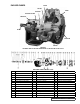
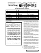
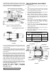
FIGURE 6 - STANDARD MECHANICAL SEAL
RIGHT SIDE
OF PUMP
SPRING ADAPTER
SEAL ACCESS HOLE (FOR SETSCREWS)
SEAL SEAT GASKET
SEAL HOLDER
SET COLLAR
SEAL
SEAT
MECHANICAL SEAL (ROTARY MEMBER)
SEAL
HOLDER
PLATE
ASSEMBLY
Standard Mechanical Seal
(Synthetic Rubber Bellows Type)
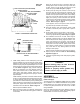
9. Loosen the four setscrews over the outer and inner end
caps. Remove both end caps, spacer collars and ball
bearing. Refer to Figure 7. The inner end cap can be
removed through the side openings in the bracket.
10. Clean all parts thoroughly and examine for wear or
damage. Check lip seals, ball bearing, bushing and idler
pin and replace if necessary. Check all other parts for
nicks, burrs, excessive wear and replace if necessary.
Wash bearings in clean solvent. Blow out bearings with
compressed air. Do not allow bearings to spin; turn them
slowly by hand. Spinning bearings will damage race
and balls. Make sure bearings are clean, then lubricate
with non-detergent SAE 30 weight oil and check for
roughness. Roughness can be determined by turning
outer race by hand.
Be sure shaft is free from nicks, burrs and foreign
particles that might damage bracket bushing. Scratches
on shaft in seal area will provide leakage paths under
mechanical seal.
11. Casing can be checked for wear or damage while
mounted on bracket.
The seal used in this pump is simple to install and good
performance will result if care is taken during installation.
The principle of the mechanical seal is contact between the
rotary and stationary members. These parts are lapped to
a high finish and their sealing effectiveness depends on
complete contact.
Viking furnishes a number of heavy-duty pumps with
special mechanical seals installed in the packing end of the
pump. These special seals are not discussed in TSM141.2.
Information is available by contacting the factory. When
requesting special seal information, be sure to give pump
model number and serial number.
1. Install bracket bushing. If bracket bushing has a
lubrication groove, install bushing with groove at 6:00
o’clock position in bracket. If carbon graphite, Refer to
Installation of Carbon Graphite Bushings, page 11.
2. Coat rotor shaft with non-detergent SAE 30 weight oil.
Start end of shaft in bracket bushing and turn from right
to left, slowly pushing until the ends of the rotor teeth are
just below the face of the casing.
3. Using a .015 inch head gasket, install head and idler
assembly on pump. Pump head and casing were marked
before disassembly to insure proper reassembly. If not, be
sure idler pin, which is offset in pump head, is positioned
toward and equal distance between port connections to
allow for proper flow of liquid through pump.
If pump is equipped with jacketed head plate, install at
this time along with new gasket.
Tighten head capscrews evenly.
If pump was equipped with a relief valve and it was
removed during disassembly, install a head with new
gaskets. Relief valve adjusting screw cap must always
point toward suction port. Refer to Figures 1, 2 and 3 on
page 1. For relief valve repair or adjustments, Refer to
Pressure Relief Valve Instructions, page 11.
4. Clean rotor shaft and bracket seal housing bore. Be sure
they are free of dirt, grit and scratches. Gently radius
leading edge of shaft diameter over which seal must be
placed.
5. Install seal set collar. Examine set collar for burrs or
scratches, and setscrews are withdrawn to prevent
shaft from being scratched when set collar is installed.
Place set collar onto shaft, push into seal chamber until
centerline of setscrews coincides with centerline of
tapped seal access holes on right side of bracket (viewed
from shaft end).
Tighten all setscrews securely to shaft. Refer to Figure
8.
6. Sealing faces on mechanical seals should not be
touched with anything but fingers or a clean cloth. A
tapered sleeve is available, at extra cost, for Q, QS and
M pumps from Viking Pump for seal installation on shaft.
Refer to Figure 9.
LS pump shaft is tapered and an installation sleeve is
not available.