
Manual


SECTION TSM 410.2
PAGE 10 OF 10
ISSUE D
VIKING PUMP, INC. • A Unit of IDEX Corporation • Cedar Falls, IA 50613 USA
© 3/2013 Viking Pump Inc.
All rights reserved
TECHNICAL SERVICE MANUAL
WARRANTY
Viking warrants all products manufactured by it to be
free from defects in workmanship or material for a
period of one (1) year from date of startup, provided
that in no event shall this warranty extend more than
eighteen (18) months from the date of shipment from
Viking. The warranty period for Universal Seal series
pumps ONLY (Universal Seal models listed below) is
three (3) years from date of startup, provided that in
no event shall this warranty extend more than forty-two
(42) months from the date of shipment from Viking.
UNDER NO CIRCUMSTANCES SHALL VIKING BE
LIABLE UNDER THIS WARRANTY OR OTHERWISE
FOR SPECIAL, INCIDENTAL, INDIRECT,
CONSEQUENTIAL OR PUNITIVE DAMAGES OF ANY
KIND, INCLUDING, BUT NOT LIMITED TO, LOST
OR UNREALIZED SALES, REVENUES, PROFITS,
INCOME, COST SAVINGS OR BUSINESS, LOST OR
UNREALIZED CONTRACTS, LOSS OF GOODWILL,
DAMAGE TO REPUTATION, LOSS OF PROPERTY,
LOSS OF INFORMATION OR DATA, LOSS OF
PRODUCTION, DOWNTIME, OR INCREASED
COSTS, IN CONNECTION WITH ANY PRODUCT,
EVEN IF VIKING HAS BEEN ADVISED OR PLACED
ON NOTICE OF THE POSSIBILITY OF SUCH
DAMAGES AND NOTWITHSTANDING THE FAILURE
OF ANY ESSENTIAL PURPOSE OF ANY PRODUCT.
THIS WARRANTY IS AND SHALL BE VIKING’S SOLE
AND EXCLUSIVE WARRANTY AND SHALL BE IN
LIEU OF ALL OTHER WARRANTIES, EXPRESS
OR IMPLIED, INCLUDING, BUT NOT LIMITED
TO, ALL WARRANTIES OF MERCHANTABILITY,
FITNESS FOR A PARTICULAR PURPOSE AND
NON-INFRINGEMENT ALL OF WHICH OTHER
WARRANTIES ARE EXPRESSLY EXCLUDED.
See complete warranty at www.vikingpump.com.
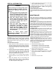
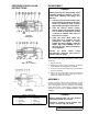
If a new spring is installed or if pressure setting of pressure
relief valve is to be changed from that which the factory has
set, the following instructions must be carefully followed.
1. Carefully remove valve cap which covers adjusting
screw.
Loosen locknut which locks adjusting screw so pressure
setting will not change during operation of pump.
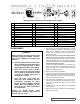
2. Install a pressure gauge in discharge line for actual
adjustment operation.
3. Turn adjusting screw in to increase pressure and out to
decrease pressure.
4. With discharge line closed at a point beyond pressure
gauge, gauge will show maximum pressure valve will
allow while pump is in operation.
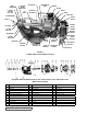
In ordering parts for pressure relief valve, always give
model number and serial number of pump as it appears on
nameplate and name of part wanted. When ordering springs,
be sure to give pressure setting desired.
PRESSURE ADJUSTMENT
IMPORTANT
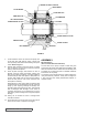
ABRASIVE LIQUID HEAVY-DUTY
BRACKET MOUNTED PUMPS
SERIES 4625
SIZES H - M