
Manual


SECTION TSM 410.2 ISSUE D PAGE 8 OF 10
DANGER !
Before starting pump, be sure all drive
equipment guards are in place.
Failure to properly mount guards may
result in serious injury or death.
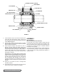
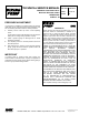
Pump
Size
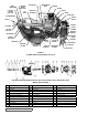
TURN OUTER END CAP C.C.W.
No. of Notches Length on O.D.
Total End
Clearance
H - HL 3 0.50 .003
K - LL 5 2.313 .005
Q - M 5 2.25 .010
10. Using a .010 to .015 inch head gasket, install head and
idler assembly on pump. Pump head and casing were
marked before disassembly to insure proper reassembly.
If not, be sure idler pin, which is offset in pump head,
is positioned toward and equal distance between port
connections to allow for proper flow of liquid through
pump.
Tighten head capscrews evenly.
Remove tapered installation sleeve from the shaft.
11. If pump is equipped with jacketed head plate, install at
this time along with new gasket.
If pump was equipped with a relief valve and was
removed during disassembly, install on head with new
gaskets. Relief valve adjusting screw cap must always
point toward suction port. Refer to Figures 1 & 2 on
Page 1. For relief valve repair or adjustments, see
Pressure Relief Valve Instructions, Page 9.
12. Slide inner spacer collar over shaft with recessed end
facing rotor. H, HL, Q and M size bearing spacer collars
are not recessed.
Place pair of half round rings on shaft and slide inner
bearing spacer collar over half round rings to lock them
in place. There is no pair of half round rings on H, HL, Q
and M size pumps. Refer to Figure 6, page 6.
13. Press lip seal, lip facing end of shaft, in inner end cap
and insert end cap through shaft end of bracket. Turn
end cap clockwise, looking at shaft end, until it engages
threads. End cap spanner wrench holes must be facing
rotor. Turn end cap with spanner wrench until it projects
slightly from opening on side of bracket. End cap must
not be turned so far that lip seal drops off end of spacer
collar on shaft or end cap becomes disengaged from
threads. Refer to Figure 6, page 6.
14. Pack ball bearing with multi-purpose grease, NLGI
#2. Place on shaft and push or gently drive in place in
bracket.
15. Press lip seal, lip facing end of shaft, in outer end cap
and insert end cap in bracket. Turn end cap in bracket
until it is tight against bearing. Refer to Figure 6, page 6.
16. Put lockwasher and locknut on shaft. Insert length of
hardwood or brass through port opening between rotor
teeth to keep shaft from turning.
Tighten locknut to 50-70 ft.– lbs. Torque (H-HL) or 100-
130 ft. – lbs. Torque (K-LL) or 170-190 ft. – lbs. Torque
(Q-M). Bend one tang of lockwasher into slot of locknut.
If tang does not line up with slot, tighten locknut until it
does. Failure to tighten locknut or engage lockwasher
tang could result in early bearing failure and cause
damage to rest of pump.
Remove length of hardwood or brass from port opening.
Adjust pump end clearance. Refer to Thrust Bearing
Adjustment.
Lubricate grease fitting over seal chamber with petroleum
jelly, petrolatum (Vasoline) or other similar low melting
point lubricant. Lubricate all other grease fittings with
multi-purpose grease, NLGI #2.
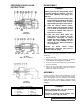
THRUST BEARING ADJUSTMENT
1. Loosen setscrews over outer and inner end caps. Two
for H and HL size pumps, four for all other sizes.
2. Turn inner end cap clockwise, viewed from shaft end, until
it projects slightly from bracket exposing approximately
three threads.
3. Turn outer end cap clockwise until rotor is tight against
head and rotor shaft cannot be turned.
4. Make a reference mark on bracket end, opposite a
notch on outer end cap. Back off outer end cap required
number of notches. Refer to Figure 11.
5. End clearances set per Step 4 are adequate for
viscosities up to 750 SSU (SAE 20 lube oil at room
temperature). Higher viscosity liquids require additional
end clearances.
As a general guideline, for viscosities between 750 and
7500 SSU (heavier lube oils) double the amount of end
clearance indicated in Step 4; for viscosities between
7500 and 75,000 SSU (e.g., resins) triple the amount.
For specific recommendations for end clearances for
viscosity or for operating temperatures above 225ºF,
check with your Viking representative or consult the
factory.
6. Tighten inner end cap with a spanner wrench. Tap
spanner wrench lightly but DO NOT OVER TIGHTEN as
it will only damage the threads.
7. Tighten all setscrews that hold inner and outer end caps
to prevent their turning in bracket.
8. Rotor and shaft should turn smoothly by hand one
complete revolution. If rotor and shaft doesn’t turn
smoothly, go back and repeat Thrust Bearing Adjustment
Steps 1 through 8.
FIGURE 11