
Manual


SECTION TSM 410.2 ISSUE D PAGE 9 OF 10
Mark valve and head before disassembly to insure proper
reassembly.
1. Remove valve cap.
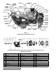
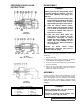
2. Measure and record length of extension of adjusting
screw. Refer to “A” on Figures 12,13 and 14.
3. Loosen locknut and back out adjusting screw until spring
pressure is released.
4. Remove bonnet, spring guide, spring and poppet from
valve body. Clean and inspect all parts for wear or
damage and replace as necessary.
Reverse procedures outlined under Disassembly. If valve
is removed for repairs, be sure to replace in same position.
Relief valve adjusting screw cap must always point towards
suction side of pump. If pump rotation is reversed, remove
relief valve and turn end for end. Refer to Figures 1, 2, and
3, page 1.
ASSEMBLY
DANGER !
Before starting pump, be sure all drive
equipment guards are in place.
Failure to properly mount guards may
result in serious injury or death.
DISASSEMBLY
DANGER !
Before opening any Viking pump liquid
chamber (pumping chamber, reservoir,
relief valve adjusting cap fitting, etc.)
Be sure:
1. That any pressure in the chamber has
been completely vented through the
suction or discharge lines or other
appropriate openings or connections.
2. That the driving means (motor,
turbine, engine, etc.) has been “locked
out” or made non-operational so that
it cannot be started while work is
being done on pump.
3. That you know what liquid the
pump has been handling and the
precautions necessary to safely
handle the liquid. Obtain a material
safety data sheet (MSDS) for the
liquid to be sure these precautions
are understood.
Failure to follow above listed
precautionary measures may result in
serious injury or death.
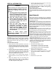
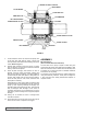
FIGURE 12
SIZE H AND HL
PRESSURE RELIEF VALVE
INSTRUCTIONS
FIGURE 13
SIZE K, KK, L, LQ AND LL
VALVE - LIST OF PARTS
1. Valve Cap 6. Valve Body
2. Adjusting Screw 7. Valve Spring
3. Lock Nut 8. Poppet
4. Spring Guide 9. Cap Gasket
5. Bonnet 10. Bonnet Gasket
FIGURE 14
SIZE Q AND M