
User Manual


SECTION TSM 443 ISSUE C PAGE 4 OF 8
CAUTION !
WHEN THE HEAD IS BEING REMOVED
FROM THE PUMP THE IDLER USUALLY
STAYS ON THE IDLER PIN, BUT WILL
FALL OFF IF THE INSIDE OF THE HEAD
IS TILTED DOWNWARD.
CAUTION !
IF THE CHECK VALVE IS LEFT OUT OF
THE DISCHARGE SIDE OF THE HEAD,
THE PUMP MUST NEVER BE RUN IN
THE OPPOSITE DIRECTION WITHOUT
INSTALLING A NEW CHECK VALVE.
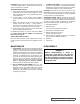
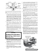
FIGURE 2
Exploded View Series 200G & 260G Pumps
ITEM NAME OF PART ITEM NAME OF PART ITEM NAME OF PART
1 Locknut 12 PressureReliefPlug 23 O-RingGasket,Head
2 Lockwasher 13 GreaseFitting 24 IdlerPin
3 EndCap,BearingHousing 14 Capscrew,Bracket 25 CheckValve
4 ClosureBearingHousing 15 BracketBushing(NeedleBearingandSnapRingonKK-250GOnly) 26 Head(ValveType)andIdlerPin
5 BearingSpacerCollar 16 MechanicalSeal 27 CapscrewforHead
6 BallBearing 17 O-RingGasket,BackFlange 28 PipePlug
7 BearingSpacerCollar,Recessed 18 Casing 29 O-RingValveGasket
8 KeeperRingHalves 19 PipePlug 30 CapscrewforValveandCoverPlate
9 BearingHousingwithSetscrews 20 RotorandShaft 31 Return-To-TankReliefValve
10 ClosureforSealChamber 21 Idler 32 CoverPlate
11 Bracket 22 IdlerBushing
DANGER !
Before opening any Viking pump liquid
chamber (pumping chamber, reservoir, relief
valve adjusting cap fitting etc.) Be sure:
1. That any pressure in the chamber has
been completely vented through the
suction or discharge lines or other
appropriate openings or connections.
2. That the driving means (motor, turbine,
engine, etc.) has been “locked out” or
made non- operational so that it cannot
be started while work is being done on
pump.
3. That you know what liquid the pump
has been handling and the precautions
necessary to safely handle the liquid.
Obtain a material safety data sheet
(MSDS) for the liquid to be sure these
precautions are understood.
Failure to follow above listed precautionary
measures may result in serious injury or
death.
1. Remove the head from the pump. Avoid damaging the
O-ring head gasket. If the pump has a relief valve on
the head, the valve may be removed, but this is not
necessary.
Always keep your feet in the clear should this part fall. A fall
on a hard surface can damage the idler. If the idler should
fall, check carefully and file or stone all nicked or rough places
before re-assembly.
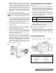
Using a pencil, inspect the check valves located at the base
of the idler pin in the head. (See Figure 3). The ball on the
inside of these fittings should be depressed with the point of
the pencil to insure that the valve is not stuck. If the spring
behind the ball does not hold the ball in a closed position, or if
the spring is broken, remove the check valve from the head.
If a defective check valve is removed from the discharge side
of the head, it need not be replaced and can be discarded.