
User Manual


SECTION TSM 443 ISSUE C PAGE 5 OF 8
However, should a defective check valve be removed from the
suction side of the head, it must be replaced with a new check
valve
2. Remove the idler and bushing assembly from the idler
pin. Replace all excessively worn parts. If it is necessary
to install a new carbon graphite bushing, extreme care
should be taken to prevent breaking when it is being
installed in the idler. If it is cracked in the idler, this
bushing will quickly disintegrate. An arbor press should
be used to install carbon graphite bushings. Be sure
bushing is started straight. DO NOT STOP the pressing
operation until the bushing is in the proper position.
Starting and stopping this operation invariably results in
a bushing failure.
3. Bend up tang on lockwasher and, using a spanner
wrench, remove the lockwasher and locknut. Hint:
A piece of wood or brass inserted between the rotor
teeth and into the casing port will prevent the rotor from
turning.
4. Drive the shaft forward approximately 0.50 inch and
inspect for the presence of a pair of half circle, round,
wire keeper rings under the inner bearing spacer collar.
If present these rings must be removed before the rotor
and shaft can be removed from the pump. Carefully
remove the rotor and shaft from the pump.
The spring and rotating member of the mechanical seal
will come out with the shaft
8. Loosen two axial setscrews in bearing housing flange
and remove the bearing housing from bracket.
9. Examine the closures in the bearing housing and end
cap. These closures are important to this assembly and
should be replaced if not in first-class condition.
When installing new closures, be sure they are
assembled with the lip facing toward the locknut –
See Figure 11.
10. The casing should be examined for wear, particularly at
the seal (area between port openings). If this surface
is in good condition, the casing in all probability may be
used
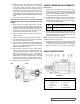
11. If KK-260-G, (See Figure 5) remove the needle bearing
from the bracket. If 200-G Series see Step 12.
Remove the stationary seal seat, being careful not to
damage the lapped surface of the seat. See Figure 7.
Using snap ring pliers, remove the snap ring located at
the end of the needle bearing. The bearing is now free
to be removed.
The bearing should be washed thoroughly and
examined. If there is any evidence of wear or damage,
a new bearing should be used.
Also examine the bearing surface on the shaft. This
surface is pitted or worn, it is strongly recommended that
a new rotor, shaft and needle bearing be installed
12. If series 200-G, the bracket bushing should be inspected
and if it shows signs of wear, should be replaced. This
carbon graphite bushing must be removed from the
casing end of the pump. If it is necessary to install a
new carbon graphite bracket bushing, the same care
should be taken as in Step 2 when replacing the carbon
graphite idler bushing
13. Mechanical Seal: If the mechanical seal in your pump
ever fails, it can be easily replaced with a new seal.
There are three basic parts to this seal. They are: the
spring, the rotary member and the stationary seal seat.
See Figures 4 or 5. Remove the spring and rotary
member from the shaft and the stationary seal seat from
the bracket. The principle of the mechanical seal is the
contact between the rotary and stationary members.
These parts are lapped to a high finish and their sealing
effectiveness depends upon complete contact
CAUTION !
UNLESS THE SEAL IS DEFECTIVE, DO
NOT REMOVE THE ROTARY MEMBER
FROM THE SHAFT. REMOVAL OF THE
SEAL WILL LIKELY CAUSE LEAKAGE
WHEN REINSTALLED.
FIGURE 3
5. Inspect the bracket closure and replace it if not in first
class condition. If this closure is replaced, be sure the
new closure is installed with the lip facing IN toward the
mechanical seal. Recent models have double lip closure
facing both ways.
6. Loosen the radial socket head set screws in outer ring
of bearing housing and remove the bearing housing end
cap, closure and bearing spacer collar. Use a spanner
wrench to remove the end cap.
7. Remove the double row ball bearing. The bearing
should be washed thoroughly and examined. If there is
any evidence of wear or damage, a new bearing should
be used.
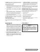
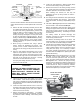
IDLER BUSHING
CHECK VALVE
(OPEN)
DISCHARGE
SIDE OF PUMP
PUMP HEAD
SUCTION
SIDE OF PUMP
CHECK VALVE
(CLOSED)
IDLER PIN
IDLER
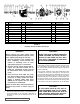
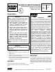
FIGURE 4
CUTAWAY VIEW 200-G SERIES
BRACKET SEAL HOUSING
SEAL SEAT GASKET
SEAL SEAT
SPRING
ROTARY MEMBER
LIPSEAL FOR SEAL CHAMBER