
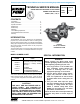
User Manual


SECTION TSM 443 ISSUE C PAGE 7 OF 8
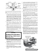
HEAD
ROTOR
2. Install the rotor and shaft. Place the end of the shaft in
the bracket bushing or needle bearing. Turn from right
to left slowly, pushing it into place, until the end of the
rotor teeth are just below the face of the casing. Placing
the head and idler on the casing will force the rotor to its
proper depth. Be sure the shaft is free from burrs and
foreign particles that might damage the bracket bushing
or needle bearing. Remove the tapered sleeve from the
shaft.
3. Place the O-ring head gasket on the head.
NOTE: BE SURE THE O-RING LOCATION ON THE HEAD
IS FREE OF DIRT AND SCALE BEFORE INSTALLING THE
O-RING
4. Place the head on the pump. With the idler on the idler
pin, put the head on the pump and tighten the capscrews.
Tilt the top of the head away from the pump slightly until
the crescent enters the inside diameter of the rotor and
rotate the idler until its teeth mesh with the rotor teeth.
This will help in putting the head on the pump.
5. Place the bearing collar on the shaft as far as it will go.
Replace keepers.
6. Install the bearing housing and closure in the bracket.
7. Pack the ball bearing with grease, place on the shaft and
push or drive into place in the housing.
8. Turn the bearing end cap (with closure and bearing collar
inside) into the bearing housing until tight against the
bearing. Lock in place by the setscrews in the outside
diameter of the bearing housing.
9. Put lockwasher and locknut on shaft. Insert length of
hardwood or brass through port opening between rotor
teeth to keep shaft from turning. Tighten locknut to 100-
130 ft. – lbs. Torque (K, KK, L, LQ, LL) . If tang does not
line up with slot, tighten locknut until it does. Failure to
tighten locknut or engage lockwasher tang could result
in early bearing failure and cause damage to pump.
Remove length of hardwood or brass from port opening.
10. Adjust the pump end clearance.
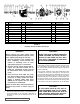
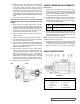
FIGURE 11
THRUST BEARING ADJUSTMENTS
(See Figure 11)
1. Loosen the two set screws “A” in the outer face of the
bearing housing “B” and turn this thrust bearing assembly
“B” clockwise until it can no longer be turned by hand.
Back off counterclockwise only until the rotor shaft can be
turned by hand with a slight noticeable drag.
2. For standard end clearance, back off the thrust bearing
assembly “B” the required number of notches or an
equivalent length measured on the outside of the bearing
housing. See the following table.
PUMP
SIZE
TURN BRG. HOUSING C.C.W. NO. OF
NOTCHES OR LENGTH ON O., INCHES
K, KK, L,
LQ & LL
4 1”
3. Tighten the two self-locking type “Allen” set screws “A”,
in the outboard face of the bearing housing, with equal
force against the bracket. Your pump is now set with
standard end clearances and locked.
NOTE: Be sure the shaft can rotate freely. If not, back off
additional notches and check again
4. For specific recommendations, consult the factory. Each
additional notch (or each 0.25”) on the outside diameter
of the bearing housing is equivalent to an extra end
clearance of .0015” on K, KK, L, LQ and LL size pumps.
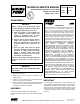
FIGURE 12
VALVE - LIST OF PARTS
1. Valve Cap 6. Valve Body
2. Adjusting Screw 7. Valve Spring
3. Lock Nut 8. Poppet
4. Spring Guide 9. Cap Gasket
5. Bonnet 10. Bonnet Gasket
VALVE INSTRUCTIONS