
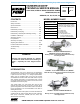
Owner's manual


Electronic copies of the most current TSM issue can be found on the Viking Pump website at www.vikingpump.com
SECTION TSM 680
PAGE 1 Of 17
ISSUE G
VIKING PUMP, INC. • A Unit of IDEX Corporation • Cedar Falls, IA 50613 USAVIKING PUMP, INC. • A Unit of IDEX Corporation • Cedar Falls, IA 50613 USA
TECHNICAL SERVICE MANUAL
CONTENTS
INTRODUCTION
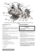
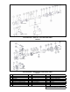
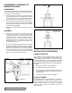
FIGURE 3 - AS, AK, AL SERIES 895 MD-C B
Introduction .................................................................. 1
Safety Information ....................................................... 2
Special Information ...................................................... 3
Maintenance ................................................................ 3-4
Disassembly of Pump .................................................. 4-7
Disassembly of Coupling ............................................. 7-9
Disassembly / Assembly MD-C Bearing Housing ........ 10
Installation of Bushings................................................ 10
Assembly of Pump....................................................... 11
Pump Rotation ............................................................. 11
Assembly of Coupling .................................................. 12-14
Adjusting End Clearance ............................................. 14
Pressure Relief Valve Instructions ............................... 15-16
Troubleshooting ........................................................... 16
Warranty ...................................................................... 17
WARNING!
Persons with surgical implants of a metallic
or electronic nature should avoid working on
pump – especially the inner magnet assem-
bly.
The illustrations used in this manual are for identification
purposes only and cannot be used for ordering parts. Obtain
a parts list from the factory or a Viking® representative.
Always give the complete name of the part, part number
and material with model number and serial number of pump
when ordering repair parts. The unmounted pump or pump
unit model number and serial number can be found on the
nameplate secured to the pump.
This manual deals only with Series 895, 893 and 897
magnetic drive pumps. Refer to Figures 1 through 44 for
general configuration and nomenclature used in this manual.
Pump specifications and recommendations are listed in
Catalog Section 680.
In the Viking model number system, the basic size letters are
combined with the series number (895, 893, 897) indicating
basic pump construction material (cast iron, steel, and,
stainless steel respectively).
MODEL NUMBER CHART
UNMOUNTED PUMPS
UNITS
Units are designated by the un-
mounted pump model numbers
followed by the magnetic coupling
size and a letter indicating drive
style.
D = Direct Drive
M = Motor Mount
B = Bearing Carrier
R = Viking Reducer Drive
P = Commercial Reducer Drive
(Example: HJ895 MD-A9 R)
GG-895, 893, 897
HJ-895, 893, 897
HL-895, 893, 897
AS-895, 893, 897
AK-895, 893, 897
AL-895, 893, 897
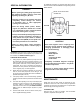
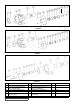
FIGURE 1 - GG, HJ, HL SERIES 893(Steel) or
SERIES 897 (Stainless Steel) MD-A B
Bearing Carrier, Footed Bracket and Mounted Pump
with Flanged Ports
Bearing Carrier, Footed Bracket and Mounted Pump
with Tapped Ports
FIGURE 2 - HJ, HL SERIES 895(Cast Iron) MD-B M
Motor Directly mounted to the Bracket and Pump with
Tapped Ports
CAST IRON, STEEL & STAINLESS STEEL PUMPS
SERIES 895, 893, 897
SIZES GG, HJ, HL, AS, AK, AL