
Owner's manual


SECTION TSM 680 ISSUE G PAGE 11 OF 17
ASSEMBLY OF PUMP
Use a suitable lubricant compatible with the fluid being
handled when reassembling the pump.
Inspect all parts, especially drilled holes in the casing for
the suck back system, to make sure they are not plugged.
Replace any worn parts, remove any burrs, and clean all
parts before assembling the pump.,
1. If the canister o-ring needs to be replaced, apply a
lubricant to the o-ring and place it into the o-ring groove.
If the o-ring is PTFE (Derivative) Encapsulated, follow
these special instructions.
Do not attempt to reuse a PTFE (Derivative) Encapulated
o-ring if it has been removed. Immerse a new o-ring in
boiling water for a few minutes. Remove it from the water
and stretch out the o-ring so it will fit onto the casing hub
without forcing it over a sharp edge. Run hot water over
the o-ring until it shrinks down tight onto the pilot of the
pump. Dry with compressed air.
2. Place the balance plate into the casing bore with
counterbores for the capscrews facing out and push it to
the bottom of the bore. Align holes to install capscrews.
Install the capscrews and tighten evenly to 10 in-lbs.
3. Clean the rotor and shaft so it is free of dirt, grit and
other debris and apply lubricant. Push it into the casing
as far as it will go.
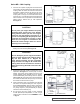
4. If the old gaskets are not reusable, refer to “ADJUSTING
HEAD GASKET END CLEARANCE” on page 14.
Otherwise, place the head gaskets on the head. The
proper amount of gaskets should be used to provide the
correct end clearance. Figure 26 gives the quantity of
gaskets available in a gasket set along with standard
end clearance. Refer to Techincal ReferenceTR-807 for
detailed instructions on setting end clearance.
PUMP MODEL
NORMAL (A) END
CLEARANCE
SET OF
GASKETS
INCLUDES
GG 895, 893 0.003
GG 897
0.005
HJ,HL 895, 893
0.005
(1) .015
(2) .007
(2) .005
HJ, HL 893, 897 0.005
AS, AK or AL 895, 893 0.005
AS, AK or AL 897 0.008
NOTE: End Clearances are adequate for viscosity’s up to
2500 SSU (SAE 40-lube oil at room temperature). Higher
viscosity’s require additional clearances. As a general rule
the end clearance is doubled for higher viscosity’s. For
specific recommendations for end clearance for viscosity or
for operating temperatures above 225 °F, check with your
Viking representative or consult the factory.
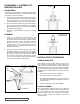
5. Coat the idler pin with a suitable lubricant and place the
idler on the idler pin in head.
6. The head can now be assembled onto the pump. Tilt the
top of the pump head away from the pump slightly until
the crescent enters the inside diameter of the rotor and
rotate the idler until its teeth mesh with the rotor teeth.
The Pump head and casing should have been marked
before disassembly to insure proper reassembly. If not,
be sure the idler pin, which is offset in the pump head,
is positioned toward and an equal distance from the port
connections to allow for proper flow of liquid through the
pump.
7. Place the key into shaft keyway and then follow the
instructions listed for assembling the appropriate size
coupling on pages 12 through 14.
CHANGING PUMP ROTATION
Cooling circulation in the pump is designed to take fluid from
the discharge side of the pump and channel it down the idler
pin into the shaft and out the far end of the shaft into the
bottom of the canister. The fluid is returned through a hole in
the casing back to the suction side of the pump. There are
generally three parts, which may need replacing or adjusting.
Technical Reference TR-112 provides additional information
about changing rotation. Contact your authorized distributor
or the factory to request a copy.
HEAD & PIN- The hole should be from the discharge side of
head to the pin. Some sizes are tapped on both sides and
the pipe plug may be moved to the other side of the head but
other models will require a new part.
BALANCE PLATE- Most designs currently are directional
and require a new part.
CASING- Some are drilled and tapped for either direction
but most feature a single hole and require a second hole for
proper return of the cooling fluid. The initial casing hole is
generally plugged or restricted with an orifice or by the new
balance plate.
Contact your local Viking distributor or the factory to
determine which parts are required.
FIGURE 26