
Owner's manual


SECTION TSM 680 ISSUE G PAGE 13 OF 17
Series MD – B15 / B40 Coupling
DANGER !
Follow these directions exactly to avoid injury
to self or damage to pumping unit. Be careful
to keep inner and outer magnets at least (1)
foot apart until step 4. Do not engage magnets
in any other fashion.
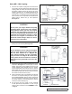
1. Inspect the magnets for any steel objects, which may
be attached. Remove any foreign material. Locate the
outer magnet assembly per dimension See Figure 32.
Apply Loctite and tighten the setscrews onto motor or
bearing carrier key and shaft.
2. If the bracket is not fastened to a base, clamp it down
See Figure 33. Mount the motor or bearing carrier to
the bracket and secure with (4) 0.5” capscrews. Reach
in and rotate the magnets by hand to make sure there is
no interference. If rubbing occurs check the dimension
in Figure 32 or contact the factory.
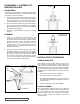
3. Install the external retaining ring and key on the pump
shaft. Slide the inner magnet assembly onto the shaft so
that it butts against the retaining ring. Install the washer,
lock washer and capscrew to secure the magnet See
Figure 34. Insert a brass bar through a port between
two rotor teeth and tighten capscrew.
4. Check to make sure the pump rotates freely by turning
the inner magnet assembly. Inspect the magnet to make
sure it has not picked up any foreign particles, which
could damage the pump. Make sure the static o-ring
is in good condition and in place. Place the canister
onto the pump and press on until it is in contact with the
pump mounting flange.
CAUTION !
Do not place fingers onto front of pump mount-
ing flange. Align canister into bore of bracket
and gently slide in. When magnets start to
engage, the unit will finish engagement on its
own very rapidly. Make sure fingers are not on
the front of the pump. See Figure 35.
5. Be certain that the power supply to the pump is “Locked-
out”. Finish assembly by securing the pump to the
bracket. See Figure 36. Check that pump rotates freely
by spinning the motor fan blades or the bearing carrier
shaft.
SETSCREWS
(2) REQUIRED
SETSCREWS
(2) REQUIRED
OUTER
MAGNET
ASSEMBLY
STANDARD
“C” FACE
MOTOR
OUTER
MAGNET
ASSEMBLY
0.5” CAPSCREWS
(WITH NUTS AND LOCK WASHERS FOR
BEARING HOUSING)
COUPLING
BRACKET
FIGURE 32
FIGURE 33
FIGURE 34
FIGURE 35
FIGURE 36
INNER MAGNET ASSEMBLY
CAPSCREW
WASHER
CANISTER O-RING
LOCK
WASHER
CANISTER
RETAINING RING
PLACE HANDS BACK HERE
DO NOT PLACE
FINGERS HERE
PUMP – BRACKET
0.5” CAPSCREWS
(4) REQUIRED
6.82
6.82