
Owner's manual


SECTION TSM 680 ISSUE G PAGE 14 OF 17
Series MD – C80 Coupling
DANGER !
Follow these directions exactly to avoid injury
to yourself or damage to the pumping unit. Be
careful to keep the inner and outer magnets at
least (1) foot apart until step 3. Do not engage
magnets in any other fashion.
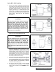
1. Inspect the magnets for any steel objects attached to
the magnets. Remove any foreign material. Place the
external retaining ring and key on the pump shaft. Slide
the inner magnet assembly onto shaft so it butts against
retaining ring. Install the washer, lock washer and
capscrew to secure the magnet. See Figure 37. Insert
a brass bar through a port between two rotor teeth and
tighten the capscrew.
FIGURE 37
FIGURE 38
FIGURE 39
FIGURE 40
0.38” CAPSCREWS
(4) REQUIRED
PUMP – BRACKET
0.5” CAPSCREWS
(4) REQUIRED
RETAINING RING
LOCK
WASHER
CANISTER
CANISTER
O-RING
WASHER
CAPSCREW
INNER MAGNET ASSEMBLY
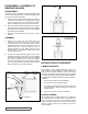
ADJUSTING HEAD GASKET END
CLEARANCE
Use the following procedure to properly adjust the end
clearance when replacing gaskets.
With the balance plate in position, slide the rotor and shaft
into the casing. Insert a feeler gage of the proper thickness
into the port and between the face of the rotor and the face of
the idler (See Figure 41). Install one 0.015” and one 0.007”
gasket onto the head. With the idler on the idler pin, place
the head into the pump casing. With the capscrews tight,
the feeler gage should fit snugly; otherwise gaskets should
be added or removed until the proper clearance is attained.
Technical Reference TR-807 will provide addtional information
about setting clearances on an internal gear pump. This
reference sheet is available through you authorized Viking
distributor or contact the factory.
2. Inspect the canister o-ring for signs of wear and replace
if necessary. Slide the canister over the inner magnet
and press it over the o-ring until the canister meets the
pump-mounting flange.
3. Support the pump from overhead and secure the
coupling bracket to avoid tipping when the pump is
attached. Using the canister as a guide, slide the
pump and magnet assembly up to the coupling bracket
through the smaller opening. Secure with the four 0.5”
capscrews. See Figure 38.
4. The outer magnet should be installed into the bearing
housing, if not refer to DISASSEMBLY/ASSEMBLY OF
BEARING HOUSING, page 10. Install the hand knobs so
that 4” of threads are projecting below housing. Support
the bearing housing from over head and gently position
the magnet over the canister so the magnet assemblies
start to engage. Evenly back out the hand knobs. See
Figure 39. The bearing housing should move toward the
bracket as the hand knobs are removed.
5. Install the (4) 0.38” capscrew. Turn the output shaft
over by hand to make sure the pump rotates freely. See
Figure 40.