
Owner's manual


SECTION TSM 680 ISSUE G PAGE 4 OF 17
MAINTENANCE (Cont.)
STORAGE:
If the pump and coupling are to be stored, the drain pump
and pour non-detergent SAE 30-weight oil into the pump port.
Apply grease to the pump or the coupling shaft extension, if
present or accessible.
Viking suggests rotating the pump shaft every 30 days to
circulate the oil in the pump. The coupling should be stored
in a dry area.
Note: If the liquid to be pumped reacts with oil, use an
acceptable alternate.
SUGGESTED REPAIR TOOLS:
The following tools are required to properly repair Series
895, 893, and 897 pumps. These tools are in addition to
standard mechanics’ tools such as open-end wrenches,
pliers, screwdrivers, etc. Most of the items can be obtained
from an industrial supply house.
1. Soft face hammer
2. Allen wrenches (for set screws)
3. External snap ring pliers - 2-810-029-375
4. Internal snap ring pliers - 2 810-047-999
5. Feeler gauge set
6. Arbor press
7. Brass bar
PUMP DISASSEMBLY
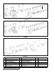
1. Refer to Figures 5, 6, 7, 8, 9 & 10 for names of parts.
2. Mark the head and casing before disassembly to insure
proper reassembly.
3. Remove the head capscrews.
Note: The four valve capscrews, valve and gasket must
be removed from the GG models before the six head
capscrews are removed.
4. Remove the head from the pump. Do not allow the idler
to fall from the idler pin. Tilt the top of the pump head
back when removing to prevent this. Avoid damaging
the head gasket set since all gaskets are required to
maintain end clearance.
5. Remove the idler and bushing assembly. If the idler
bushing needs to be replaced, see “INSTALLATION
OF BUSHINGS” on page 10. If further disassembly is
required, the pump must be separated from coupling.
Refer to “DISASSEMBLY OF COUPLING” on pages
7-9 before proceeding with Step 6.
WARNING!
Refer to DANGER & CAUTION listed on page 2
before proceeding.
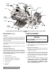
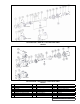
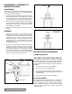
ROTOR
HEAD
IDLER PIN
RELIEF
VALVE
HEAD
GASKET
SEAL
CASING
IDLER
CUTAWAY VIEW MAG DRIVE PUMP, MODEL HL 893 MD-B B ILLUSTRATED. (TYPICAL OF GG-HL SIZES)
RETAINING
RING
INNER
MAGNET
ASSEMBLY
BRACKET
OUTER
MAGNET
ASSEMBLY
SHAFT
BEARING
CARRIER
ASSEMBLY
CANISTER
TEMPERATURE
PROBE
CANISTER
O-RING
CASING
BUSHING
BALANCE
PLATE
FIGURE 5