
Owner's manual


SECTION TSM 680 ISSUE G PAGE 7 OF 17
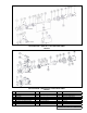
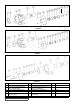
PUMP DISASSEMBLY
6. With the inner magnet removed, now remove the
key (not required on AS, AK or AL) and the external
retaining ring from the shaft. The rotor and shaft may
now be removed by tapping on the end of the shaft
with a soft face hammer (If a soft face hammer is not
available a regular hammer may be used with a piece of
hardwood).
7. Remove the balance plate capscrews and pull the
balance plate out.
The casing should be examined for wear, particularly in the
area between ports. All parts should be checked for wear
before the pump is reassembled.
When making major repairs, such as replacing a rotor
and shaft, it is advisable to also install a new head and
idler pin, idler and bushing, and casing bushings. See
“INSTALLATION OF BUSHINGS” on page 10.
Clean all parts thoroughly and examine for wear or damage.
Check bushings, idler pin and balance plate; replace if
necessary.
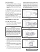
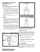
DISASSEMBLY OF COUPLING
Series MD - A4 / A9 Coupling
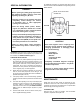
1. Remove piping to ports and remove the capscrews-
securing pump to bracket. See Figure 11. Support the
pump with an overhead hoist if possible.
CAUTION !
Do not place fingers onto front of pump mount-
ing flange or face of bracket. Using extreme
caution, pull inner magnet away from outer
magnet. See Figure 12. If you do not complete-
ly pull the pump out it will snap back and could
pinch a finger or hand. Once the inner magnet
is removed from the bracket be careful setting
it down as it will attract any steel object.
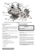
2. The canister will probably be full of liquid, therefore use
care while removing from the pump and pull straight off.
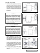
3. Remove the external retaining ring (closest to the end of
the shaft) and slide off the inner magnet assembly (See
Figure 13). Do not forget this is a very strong magnet. If
pump disassembly is required, remove second external
retaining ring.
4. Do not remove the o-ring unless it is bad, especially
PTFE (Derivative) Encapsulated. If a new o-ring is
required, follow instructions in the ASSEMBLY section
on page 11.
5. You should be able to visually inspect the outer magnets
from the end of the bracket. If removal is necessary, start
by removing the (4) capscrews (See Figure 14) and
separating the bracket from the motor or bearing carrier.
Loosen the setscrew on the motor (or bearing carrier)
shaft and pull the outer magnet assembly off. If the
unit features a bearing carrier, the bearings should not
require maintenance since they are sealed. If necessary,
disassemble by removing the single internal retaining
ring (See Figure 8) then press the shaft and bearings
out of the housing. Remove the external retaining rings
from the shaft to remove bearings.
PUMP – BRACKET
0.38” CAPSCREWS
(2) REQUIRED
PLACE HANDS BACK HERE
DO NOT PLACE
FINGERS HERE
RETAINING RINGS
INNER MAGNET ASSEMBLY
STATIC O-RING
CANISTER
CAPSCREWS
(4) REQUIRED
SETSCREWS
(2) REQUIRED
COUPLING
BRACKET
FIGURE 11
FIGURE 12
FIGURE 13
FIGURE 14