Viking eUSB Embedded USB Manual ~ Industrial Products Manual PSFDUC3XXXXYXX Revision B www.vikingtechnology.
Revision History Date Revision A 9/12/14 B 9/16/14 Manual PSFDUC3XXXXYXX Revision B www.vikingtechnology.com Description Initial release VRFDUC3(L)032GYCNxx PN for SM3252 VRFDUC3032GYCNE1 (12/13/2013) Update PN table for new PN’s and 16GB (A1, 6/2/2014) Revised Standby Current and Operating Current based on 3.3V NAND devices (A2, 7/8/14) Removed firmware upgrade capability (A3, 8/8/14) Add VRFDUC31024YCG PN.
Legal Information Legal Information Copyright© 2014 Sanmina Corporation. All rights reserved. The information in this document is proprietary and confidential to Sanmina Corporation. No part of this document may be reproduced in any form or by any means or used to make any derivative work (such as translation, transformation, or adaptation) without written permission from Sanmina.
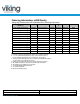
Ordering Information: eUSB Family Viking High Performance USB embedded Drive Ordering Information Part Number Version-1 ( four flash placements) VRFDUC3(L)1024YxE3yy VRFDUC3(L)2048YxE3yy VRFDUC3(L)4096YxH3yy VRFDUC3(L)8192YxK3yy VRFDUC3(L)016GYxK3yy VRFDUC3(L)032GYxN3yy Capacity 1GB 2GB 4GB 8GB 16GB 32GB Device Density 8Gb 8Gb 16Gb 32Gb 32Gb 64Gb Voltage 3.3 3.3 3.3 3.3 3.3 3.
Table of Contents 1 INTRODUCTION 7 1.1 Product Overview 7 1.2 Features 7 1.3 Block Diagram 8 1.4 USB Interface 9 2 PRODUCT SPECIFICATIONS 9 2.1 Performance 9 2.2 Timing 9 2.3 Power-up AC timing Requirements 9 2.4 Electrical Characteristics 2.4.1 Absolute Maximum Ratings 2.4.2 DC Operating Conditions and Characteristics 2.4.3 Power Consumption 2.4.4 Capacitance 10 10 10 10 11 2.5 Environmental Conditions 2.5.1 Temperature and Altitude 11 11 2.
Table of Tables Table 2-1: Maximum Sustained Read and Write Bandwidth _____________________________ 9 Table 2-2: Timing Specifications __________________________________________________ 9 Table 2-3: Absolute Maximum Ratings ____________________________________________ 10 Table 2-4: Voltage and Current Ratings ____________________________________________ 10 Table 2-5: Power Consumption __________________________________________________ 11 Table 2-6: Bus Line Capacitance ______________________________________
1 Introduction 1.1 Product Overview Viking Technology’s Embedded USB (eUSB) module provides a rugged, reliable and cost effective non-volatile memory, solutions to OEM customers in the Communication, Networking, Embedded and Industrial markets. The eUSB module is a secure pluggable device and a drop-in replacement for Intel® ZU130 Value Solid State Drive with a USB 2.0 interface, ECC and global wearleveling. Additional options such as MLC (Multi Level Cell) technology and ESD protection are also available.
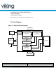
• • • Solid state, Non-volatile NAND Memory RoHS Compliant Static Wear Leveling * With exception of 3.3V only operation, USB specification is 5V. 1.3 Block Diagram Figure 1-1: High-Level Block Diagram USB/NAND CONTROLLER VOLTAGE REGULATOR 5V – 3.3V 3.3V 5.0V 5V RAM BUFFER LOCAL MICROPROCESSOR USB ENDPOINT CONTROLLER HOST CONNECTOR DM ` FLASH NAND DP DATA BUFFER GND #ACTIVE FLASH MEMORY INTERFACE (DUAL CHANNEL) ECC OSCILLATOR Manual PSFDUC3XXXXYXX Revision B www.vikingtechnology.
1.4 USB Interface • • • The USB interface is compliant with the USB 2.0 specification. The USB interface connects the host computer to the embedded USB. The USB interface runs at a maximum speed of 2.0 Gbps (gigabits per second). If the host computer is unable to negotiate a speed of 2.0 Gbps, the USB interface automatically renegotiates to lower speeds. 2 Product Specifications 2.1 Performance The host interface speed is 60MB/s with a read/write bandwidth shown in the following tables.
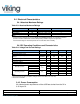
2.4 Electrical Characteristics 2.4.1 Absolute Maximum Ratings Table 2-3: Absolute Maximum Ratings Parameter Symbol Value Unit 5.0 Supply Voltage VBUS -0.3 ~ 5.5 V 3.3 Supply Voltage VBUS -0.3 ~ 4.0 V Input Voltage VIN GND - 0.5 ~ VCC + 0.5 V Storage Temperature TST -55 ~ 150 °C Notes: 1. Permanent device damage may occur if ‘ABSOLUTE MAXIMUM RATINGS’ are exceeded. Functional operation should be restricted to recommended operating condition.
Table 2-5: Power Consumption Power Standby Operating Typical 1 450 units mW mW 2.4.4 Capacitance Table 2-6: Bus Line Capacitance Parameter Bus line capacitance Symbol Min Max Unit CL - 20 pF 2.5 Environmental Conditions 2.5.
Parameter Read Endurance 3 Write or Erase Endurance Wear-leveling Data retention Value Unlimited (specified by the flash component) Global >10 years Notes: 1. MTBF is calculated based on a Part Stress Analysis. It assumes nominal voltage, with all other o parameters within specified range. Telcordia method SR-332 component FIT rate at 55 c. 2. Power On/Off Cycles defined as power being removed from the drive, and then restored.
3 Mechanical Information The dimensions of the eUSB (version-1) are based on the following PCB #s: 1208, 1209 As an example, the 1208 PCB would have a 0001208A marking that is silkscreened at the bottom edge of the PCB near the mounting hole on the same side as the connector (at bottom side of the eUSB) as shown in the following figure. Figure 3-1: Location of PCB # marking PCB # Manual PSFDUC3XXXXYXX Revision B www.vikingtechnology.
Figure 3-2: Dimensions (Version-1) See Note 5 See Note 5 Notes: 1. PCB number is silkscreened on the PCB 2. Dimensions shown in millimeters [inches] 3. Max screw penetration is 5mm at all 4 locations. 4. The module connector height is 7.4 ± 0.13 [0.290± 0.005] plus standoff ~ 0.45mm ± 0.13 when mounted to a PCB. 5. Connector height with standoff is 8.00± 0.13 [0.315± 0.005] Manual PSFDUC3XXXXYXX Revision B www.vikingtechnology.
The dimensions of the eUSB (version 2) are based on the following PCB #s: 1448, 1449 Figure 3-3: Dimensions (Version-2, low profile) PCB thickness Primary Side (Top View) (Bottom View) Overall thickness Side View Low profile Module Connector: SAMTEC SMM-105-02-F-D-LC-09-P-TR Pitch: 2.00mm Secondary Side Manual PSFDUC3XXXXYXX Revision B www.vikingtechnology.
Figure 3-4: Dimensions (Version 2, standard profile) PCB thickness See Note 4 Primary Side (Top View) (Bottom View) Overall thickness Side View Notes: 1. Standard Profile Module Connector: SAMTEC SSM-105-L-DV-LC-009-P-TR Pitch: 2.54mm 2. Dimensions shown in millimeters 3. Max screw penetration is 5mm at all 4 locations. 4. The module connector height is 7.4 ± 0.13 [0.290± 0.005] Secondary Side Manual PSFDUC3XXXXYXX Revision B www.vikingtechnology.
4 Pin and Signal Descriptions Figure 4-1: Connector Pin Assignments 4.1 Signal and Power Description Tables Table 4-1: eUSB Connector Pin Signal Definitions Pin 1 2 3 4 5 6 7 8 9 Signal Name VBUS NC DM NC DP NC GND NC N/A Type Power NC I/O NC I/O NC Power NC Key 10 #Activity I/O Description 3.3 or 5V power supply Not connected USB 2.0 Data Negative Pin Not connected USB 2.0 Data Positive Pin Not connected Ground Not connected Polarization Status signal that indicates when the drive is busy.
5 Certifications and Compliance Table 5-1: Device Certifications Certification/Compliance RoHS EU WEEE Compliant Safety Description Viking Technology, Sanmina Corporation ("Viking") shall use commercially reasonable efforts to provide components, parts, materials, products and processes to customers that do not contain: (i) lead, mercury, hexavalent chromium, polybrominated biphenyls (PBB) and polybrominated diphenyl ethers (PBDE) above 0.1% by weight in homogeneous material or (ii) cadmium above 0.