
Service manual

SECTION TSM 845.1 ISSUE C PAGE 10 OF 13
PUMP ASSEMBLY
Use a lubricant compatible with the fluid being handled when
reassembling the pump.
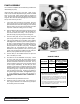
Inspect all parts, replacing any worn parts. Polish out any
nicks or burrs and clean all parts thoroughly. Make sure drilled
holes in rotor, shaft, orifice, balance plate and bracket are
clear. Plugged areas will cause heat buildup and destroy the
magnets. Also check the drilled passageways in the head and
idler pin to be sure they are clear.
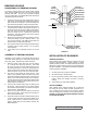
1. If the casing was removed from the bracket, place the
O-ring into the groove on back mounting face of casing
(side closest to the hole for the locating pin), and carefully
slide the casing onto the pilot of the bracket and install
capscrews. Install the locating pin into the casing.
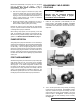
2. Place the balance plate into the casing bore with grooved
side out. Orient the groove toward the discharge port.
Push to the bottom of the casing. Line up the notch in
plate with the pin projecting through the casing bore.
3. Insert the shaft gently into the inner bushing bore and
push through until rotor is up against the balance plate.
4. If the old head gaskets are not reusable, refer to Gasket
Table Figure 18. Otherwise, place all head gaskets on
the head. Proper placement of the head is achieved by
the correct number of gaskets. Improper placement will
adversely affect the operation of the pump. The Gasket
Table shows the recommended end clearance and
itemizes the content of gaskets in a set. The O-ring is the
primary seal and should be installed onto the head pilot
after the proper gaskets have been put in place.
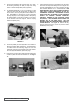
5. Coat the idler pin with suitable lubricant and place the
idler on the idler pin in head.
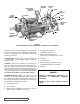
6. The head can now be assembled on the pump. Tilt the
top of the head away from the pump slightly until the
crescent enters the inside diameter of the rotor and rotate
the idler until its teeth mesh with the rotor teeth. Line up
mark on head and casing, which were previously marked
to insure proper reassembly. Be sure idler pin, which
is offset in pump head, is positioned toward and equal
distance between port connections to allow for proper flow
of liquid through pump. Tighten the head capscrews (or
nuts onto studs in the Q size). Check the end clearance
using a feeler gage as illustrated. See Figure 20 on page
11. If end clearance is not correct, refer to section on
ADJUSTING HEAD GASKET END CLEARANCE on
page 11.
7. Install relief valve if provided and removed.
8. Install the snap ring onto the shaft (not required on Q
size). Apply a lubricant to the canister O-ring and place
into the face groove in the bracket.
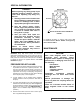
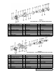
FIGURE 16
FIGURE 17
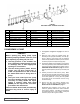
FIGURE 18
GASKET TABLE
PUMP MODEL
NORMAL ➀
END
CLEARANCE
ONE SET OF
GASKETS CONSISTS
OF THE FOLLOWING
LQ & LS-825 .008
(1) .015
(2) .007
(2) .005
Q & QS-825 .010
(1) .015
(2) .007
(3) .005
End clearances are adequate for viscosities up to 750 SSU
(SAE 20-lube oil at room temperature). Higher viscosity
liquids require additional end clearances.
As a general guideline, for viscosities between 750 and 7500
SSU (heavier lube oils) add an additional 50% of the end
clearance listed, for viscosities between 7500 and 25,000 SSU
(e.g., resins) double the amount indicated.
For specific recommendations for end clearances for viscosity
or for operating temperatures above 225ºF, check with your
Viking representative or consult the factory.
➀