
Service manual


SECTION TSM 845.1 ISSUE C PAGE 11 OF 13
2. Place a spacer under pump so the foot sits flat and clamp
foot to the table. Install one of the secondary O-Ring
seals onto the pump pilot then slide the coupling bracket
up to pump and bolt together.
3. Install two threaded rods into the bracket on the other
end. Insert the (2) jackscrews into their holes of the
bearing housing and thread in completely. Install other
secondary O-ring onto the bearing housing pilot. Support
the bearing housing assembly from over head then slide
onto the (2) threaded rods. Balance the assembly and
glide outer magnet onto canister until jackscrews come
to rest in the two counter bored holes on the bracket. BE
CAREFUL TO CENTER THE OUTER MAGNET WHILE
STARTING TO ENGAGE CANISTER. Depending
on lengths of magnets the unit may be drawn in as the
jackscrews are removed or may require pushing in.
Evenly back off the jack screws until the housing is
approximately 1” from the bracket then remove the over
head support and finish backing off the jack screws. The
housing may require a slight lift to get into the pilot of the
bracket. Secure with (2) capscrews then remove the rods
and install final (2) capscrews.
ADJUSTING HEAD GASKET END
CLEARANCE
Use either of the following procedures to properly adjust the
end clearance, when replacing gaskets.
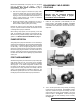
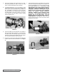
PROCEDURE A:
With the casing secured to the bracket and balance plate in
position, slide the rotor and shaft into the casing. Insert the
feeler gage of the proper thickness into the port and between
two rotor teeth. Install one .015” and .007” gasket onto the
head. With the idler on idler pin, place head into the pump
casing. With capscrews tight, the feeler gage should fit snugly;
otherwise gaskets should be added or removed until the
proper clearance is attained. See Figure 19.
FIGURE 19
FIGURE 20
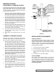
PROCEDURE B:
If the pump is in the pipeline and not accessible through ports,
remove the head and remove gaskets. Put the head back
on and measure the gap as shown. See Figure 20. After
determining the gap between head and casing, select a
combination of gaskets with approximately 25% more total
thickness than the feeler gage plus required end clearance.
See Figure 18 on page 10. Note: gaskets will compress
when head is tightened down. Remove head, install all
gaskets and the O-ring, and then install head. Tighten the
head capscrews and then check the pump by making sure
the pump turns over freely by hand.
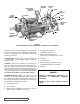
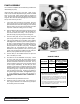
ASSEMBLY: D SERIES COUPLING
1. Remove any foreign material attached to the magnets.
Place key in pump shaft and slide inner magnet on shaft
until it comes to rest against shoulder on shaft. Insert
washer, lockwasher and capscrew into end of magnet
and tighten. May require inserting brass bar into port to
block rotor from turning. Install O-ring into face of pump
bracket then slide canister over inner magnet and secure
with the capscrews.
DANGER !
Follow these directions exactly to avoid
injury to self or damage to pumping unit,
be extremely careful to keep inner & outer
magnets at least (1) foot apart until step
3. Do not allow magnets to engage in any
other fashion. Be aware of health hazards
listed on (page 2).
DANGER !
Before starting pump, be sure all drive
equipment guards are in place.
Failure to properly mount guards may
result in serious injury or death.